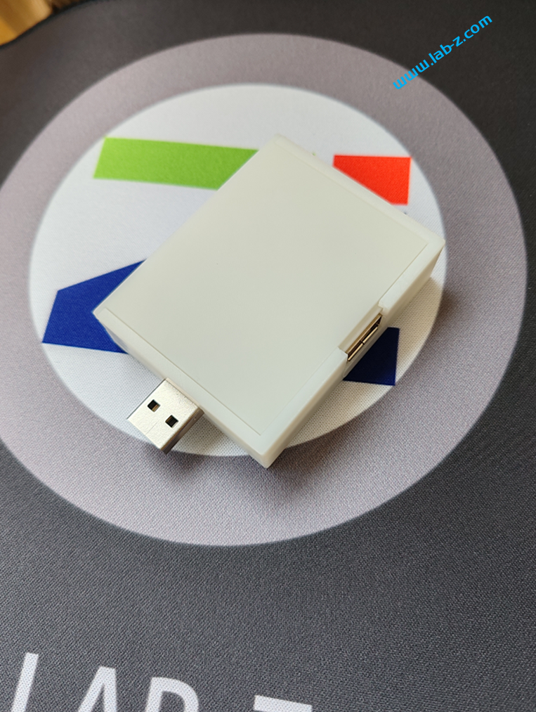
Rapoo(雷柏) V820是一款游戏机械键盘,采用雷柏自主机械轴,双色注塑键帽,5个独立游戏G键,全尺寸一体式掌托,USB口109键无冲突,109键可编程,12种背光模式,加厚金属上盖。
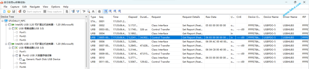
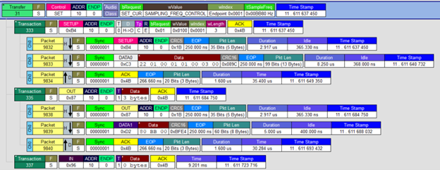
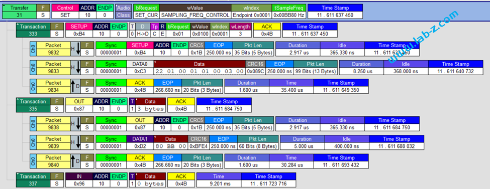
它自带了一个颜色控制的程序,经过研究总结出了它的控制方法。使用 USBLyzer 抓取它设置的动作发现应用程序会对设备发送几个 Package。
经过多次实验,确定了2个 Pacakge 是必须的,发送之后键盘会改变LED颜色。第一个是下面代码中的cmdBuffer定义的,第二个是LedBuffer中定义的,所有颜色信息都是通过这个提供给键盘的。LedBuffer[8] 开始是按键的Blue;LedBuffer[140]开始是按键的 Red取值;LedBuffer[272] 开始为 Green 取值。
按键偏移总结如下:
#include <stdio.h>
#include <wchar.h>
#include <string.h>
#include <stdlib.h>

#include "hidapi.h"


int Asc2KeyLEDOffset(char asc) {
	int KeyOffset;
	switch (asc) {
	case '~':
	case '`':
		KeyOffset = 30;
		break;
	case '!':
	case '1':
		KeyOffset = 31;
		break;
	case '@':
	case '2':
		KeyOffset = 32;
		break;
	case '#':
	case '3':
		KeyOffset = 33;
		break;
	case '$':
	case '4':
		KeyOffset = 34;
		break;
	case '%':
	case '5':
		KeyOffset = 35;
		break;
	case '^':
	case '6':
		KeyOffset = 36;
		break;
	case '&':
	case '7':
		KeyOffset = 37;
		break;
	case '*':
	case '8':
		KeyOffset = 38;
		break;
	case '(':
	case '9':
		KeyOffset = 39;
		break;
	case ')':
	case '0':
		KeyOffset = 40;
		break;
	case '_':
	case '-':
		KeyOffset = 41;
		break;
	case '+':
	case '=':
		KeyOffset = 42;
		break;
	case 'Q':
	case 'q':
		KeyOffset = 53;
		break;
	case 'W':
	case 'w':
		KeyOffset = 54;
		break;
	case 'E':
	case 'e':
		KeyOffset = 55;
		break;
	case 'R':
	case 'r':
		KeyOffset = 56;
		break;
	case 'T':
	case 't':
		KeyOffset = 57;
		break;
	case 'Y':
	case 'y':
		KeyOffset = 58;
		break;
	case 'U':
	case 'u':
		KeyOffset = 59;
		break;
	case 'I':
	case 'i':
		KeyOffset = 60;
		break;
	case 'O':
	case 'o':
		KeyOffset = 61;
		break;
	case 'P':
	case 'p':
		KeyOffset = 62;
		break;
	case '{':
	case '[':
		KeyOffset = 63;
		break;
	case '}':
	case ']':
		KeyOffset = 64;
		break;
	case '|':
	case '\\':
		KeyOffset = 65;
		break;
	case 'A':
	case 'a':
		KeyOffset = 75;
		break;
	case 'S':
	case 's':
		KeyOffset = 76;
		break;
	case 'D':
	case 'd':
		KeyOffset = 77;
		break;
	case 'F':
	case 'f':
		KeyOffset = 78;
		break;
	case 'G':
	case 'g':
		KeyOffset = 79;
		break;
	case 'H':
	case 'h':
		KeyOffset = 80;
		break;
	case 'J':
	case 'j':
		KeyOffset = 81;
		break;
	case 'K':
	case 'k':
		KeyOffset = 82;
		break;
	case 'L':
	case 'l':
		KeyOffset = 83;
		break;
	case ':':
	case ';':
		KeyOffset = 84;
		break;
	case '"':
	case '\'':
		KeyOffset = 85;
		break;
	case 'Z':
	case 'z':
		KeyOffset = 98;
		break;
	case 'X':
	case 'x':
		KeyOffset = 99;
		break;
	case 'C':
	case 'c':
		KeyOffset = 100;
		break;
	case 'V':
	case 'v':
		KeyOffset = 101;
		break;
	case 'B':
	case 'b':
		KeyOffset = 102;
		break;
	case 'N':
	case 'n':
		KeyOffset = 103;
		break;
	case 'M':
	case 'm':
		KeyOffset = 104;
		break;
	case '<':
	case ',':
		KeyOffset = 105;
		break;
	case '>':
	case '.':
		KeyOffset = 106;
		break;
	case '?':
	case '/':
		KeyOffset = 107;
		break;
	case ' ':
		KeyOffset = 123;
		break;

	default:
		KeyOffset = 0;
		break;
	}
	return KeyOffset;
}

//#pragma comment (lib,"setupapi.lib")//hidapi所需的lib环境,没有此文件会导致链接错误

// Headers needed for sleeping.
#ifdef _WIN32
#include <windows.h>
#else
#include <unistd.h>
#endif

// Fallback/example
#ifndef HID_API_MAKE_VERSION
#define HID_API_MAKE_VERSION(mj, mn, p) (((mj) << 24) | ((mn) << 8) | (p))
#endif
#ifndef HID_API_VERSION
#define HID_API_VERSION HID_API_MAKE_VERSION(HID_API_VERSION_MAJOR, HID_API_VERSION_MINOR, HID_API_VERSION_PATCH)
#endif

//
// Sample using platform-specific headers
#if defined(__APPLE__) && HID_API_VERSION >= HID_API_MAKE_VERSION(0, 12, 0)
#include <hidapi_darwin.h>
#endif

#if defined(_WIN32) && HID_API_VERSION >= HID_API_MAKE_VERSION(0, 12, 0)
#include "hidapi_winapi.h"
#endif

#if defined(USING_HIDAPI_LIBUSB) && HID_API_VERSION >= HID_API_MAKE_VERSION(0, 12, 0)
#include <hidapi_libusb.h>
#endif
//

int res;

unsigned char cmdBuffer[5] = { 0x05, 0x83, 0x00,  0x00, 0x00 };

unsigned char LedBuffer[1032] = {
0x06, 0x09, 0xac, 0x00, 0x40, 0x00, 0x00, 0x00, 0x00, 0x00, 0x00, 0x00, 0x00, 0x00, 0x00, 0x00,
0x00, 0x00, 0x00, 0x00, 0x00, 0x00, 0x00, 0x00, 0x00, 0x00, 0x00, 0x00, 0x00, 0x00, 0x00, 0x00,
0x00, 0x00, 0x00, 0x00, 0x00, 0x00, 0x00, 0x00, 0x00, 0x00, 0x00, 0x00, 0x00, 0x00, 0x00, 0x00,
0x00, 0x00, 0x00, 0x00, 0x00, 0x00, 0x00, 0x00, 0x00, 0x00, 0x00, 0x00, 0x00, 0x00, 0x00, 0x00,
0x00, 0x00, 0x00, 0x00, 0x00, 0x00, 0x00, 0x00, 0x00, 0x00, 0x00, 0x00, 0x00, 0x00, 0x00, 0x00,
0x00, 0x00, 0x00, 0x00, 0x00, 0x00, 0x00, 0x00, 0x00, 0x00, 0x00, 0x00, 0x00, 0x00, 0x00, 0x00,
0x00, 0x00, 0x00, 0x00, 0x00, 0x00, 0x00, 0x00, 0x00, 0x00, 0x00, 0x00, 0x00, 0x00, 0x00, 0x00,
0x00, 0x00, 0x00, 0x00, 0x00, 0x00, 0x00, 0x00, 0x00, 0x00, 0x00, 0x00, 0x00, 0x00, 0x00, 0x00,
0x00, 0x00, 0x00, 0x00, 0x00, 0x00, 0x00, 0x00, 0x00, 0x00, 0x00, 0x00, 0x00, 0x00, 0x00, 0x00,
0x00, 0x00, 0x00, 0x00, 0x00, 0x00, 0x00, 0x00, 0x00, 0x00, 0x00, 0x00, 0x00, 0x00, 0x00, 0x00,
0x00, 0x00, 0x00, 0x00, 0x00, 0x00, 0x00, 0x00, 0x00, 0x00, 0x00, 0x00, 0x00, 0x00, 0x00, 0x00,
0x00, 0x00, 0x00, 0x00, 0x00, 0x00, 0x00, 0x00, 0x00, 0x00, 0x00, 0x00, 0x00, 0x00, 0x00, 0x00,
0x00, 0x00, 0x00, 0x00, 0x00, 0x00, 0x00, 0x00, 0x00, 0x00, 0x00, 0x00, 0x00, 0x00, 0x00, 0x00,
0x00, 0x00, 0x00, 0x00, 0x00, 0x00, 0x00, 0x00, 0x00, 0x00, 0x00, 0x00, 0x00, 0x00, 0x00, 0x00,
0x00, 0x00, 0x00, 0x00, 0x00, 0x00, 0x00, 0x00, 0x00, 0x00, 0x00, 0x00, 0x00, 0x00, 0x00, 0x00,
0x00, 0x00, 0x00, 0x00, 0x00, 0x00, 0x00, 0x00, 0x00, 0x00, 0x00, 0x00, 0x00, 0x00, 0x00, 0x00,
0x00, 0x00, 0x00, 0x00, 0x00, 0x00, 0x00, 0x00, 0x00, 0x00, 0x00, 0x00, 0x00, 0x00, 0x00, 0x00,
0x00, 0x00, 0x00, 0x00, 0x00, 0x00, 0x00, 0x00, 0x00, 0x00, 0x00, 0x00, 0x00, 0x00, 0x00, 0x00,
0x00, 0x00, 0x00, 0x00, 0x00, 0x00, 0x00, 0x00, 0x00, 0x00, 0x00, 0x00, 0x00, 0x00, 0x00, 0x00,
0x00, 0x00, 0x00, 0x00, 0x00, 0x00, 0x00, 0x00, 0x00, 0x00, 0x00, 0x00, 0x00, 0x00, 0x00, 0x00,
0x00, 0x00, 0x00, 0x00, 0x00, 0x00, 0x00, 0x00, 0x00, 0x00, 0x00, 0x00, 0x00, 0x00, 0x00, 0x00,
0x00, 0x00, 0x00, 0x00, 0x00, 0x00, 0x00, 0x00, 0x00, 0x00, 0x00, 0x00, 0x00, 0x00, 0x00, 0x00,
0x00, 0x00, 0x00, 0x00, 0x00, 0x00, 0x00, 0x00, 0x00, 0x00, 0x00, 0x00, 0x00, 0x00, 0x00, 0x00,
0x00, 0x00, 0x00, 0x00, 0x00, 0x00, 0x00, 0x00, 0x00, 0x00, 0x00, 0x00, 0x00, 0x00, 0x00, 0x00,
0x00, 0x00, 0x00, 0x00, 0x00, 0x00, 0x00, 0x00, 0x00, 0x00, 0x00, 0x00, 0x00, 0x00, 0x00, 0x00,
0x00, 0x00, 0x00, 0x00, 0x00, 0x00, 0x00, 0x00, 0x00, 0x00, 0x00, 0x00, 0x00, 0x00, 0x00, 0x00,
0x00, 0x00, 0x00, 0x00, 0x00, 0x00, 0x00, 0x00, 0x00, 0x00, 0x00, 0x00, 0x00, 0x00, 0x00, 0x00,
0x00, 0x00, 0x00, 0x00, 0x00, 0x00, 0x00, 0x00, 0x00, 0x00, 0x00, 0x00, 0x00, 0x00, 0x00, 0x00,
0x00, 0x00, 0x00, 0x00, 0x00, 0x00, 0x00, 0x00, 0x00, 0x00, 0x00, 0x00, 0x00, 0x00, 0x00, 0x00,
0x00, 0x00, 0x00, 0x00, 0x00, 0x00, 0x00, 0x00, 0x00, 0x00, 0x00, 0x00, 0x00, 0x00, 0x00, 0x00,
0x00, 0x00, 0x00, 0x00, 0x00, 0x00, 0x00, 0x00, 0x00, 0x00, 0x00, 0x00, 0x00, 0x00, 0x00, 0x00,
0x00, 0x00, 0x00, 0x00, 0x00, 0x00, 0x00, 0x00, 0x00, 0x00, 0x00, 0x00, 0x00, 0x00, 0x00, 0x00,
0x00, 0x00, 0x00, 0x00, 0x00, 0x00, 0x00, 0x00, 0x00, 0x00, 0x00, 0x00, 0x00, 0x00, 0x00, 0x00,
0x00, 0x00, 0x00, 0x00, 0x00, 0x00, 0x00, 0x00, 0x00, 0x00, 0x00, 0x00, 0x00, 0x00, 0x00, 0x00,
0x00, 0x00, 0x00, 0x00, 0x00, 0x00, 0x00, 0x00, 0x00, 0x00, 0x00, 0x00, 0x00, 0x00, 0x00, 0x00,
0x00, 0x00, 0x00, 0x00, 0x00, 0x00, 0x00, 0x00, 0x00, 0x00, 0x00, 0x00, 0x00, 0x00, 0x00, 0x00,
0x00, 0x00, 0x00, 0x00, 0x00, 0x00, 0x00, 0x00, 0x00, 0x00, 0x00, 0x00, 0x00, 0x00, 0x00, 0x00,
0x00, 0x00, 0x00, 0x00, 0x00, 0x00, 0x00, 0x00, 0x00, 0x00, 0x00, 0x00, 0x00, 0x00, 0x00, 0x00,
0x00, 0x00, 0x00, 0x00, 0x00, 0x00, 0x00, 0x00, 0x00, 0x00, 0x00, 0x00, 0x00, 0x00, 0x00, 0x00,
0x00, 0x00, 0x00, 0x00, 0x00, 0x00, 0x00, 0x00, 0x00, 0x00, 0x00, 0x00, 0x00, 0x00, 0x00, 0x00,
0x00, 0x00, 0x00, 0x00, 0x00, 0x00, 0x00, 0x00, 0x00, 0x00, 0x00, 0x00, 0x00, 0x00, 0x00, 0x00,
0x00, 0x00, 0x00, 0x00, 0x00, 0x00, 0x00, 0x00, 0x00, 0x00, 0x00, 0x00, 0x00, 0x00, 0x00, 0x00,
0x00, 0x00, 0x00, 0x00, 0x00, 0x00, 0x00, 0x00, 0x00, 0x00, 0x00, 0x00, 0x00, 0x00, 0x00, 0x00,
0x00, 0x00, 0x00, 0x00, 0x00, 0x00, 0x00, 0x00, 0x00, 0x00, 0x00, 0x00, 0x00, 0x00, 0x00, 0x00,
0x00, 0x00, 0x00, 0x00, 0x00, 0x00, 0x00, 0x00, 0x00, 0x00, 0x00, 0x00, 0x00, 0x00, 0x00, 0x00,
0x00, 0x00, 0x00, 0x00, 0x00, 0x00, 0x00, 0x00, 0x00, 0x00, 0x00, 0x00, 0x00, 0x00, 0x00, 0x00,
0x00, 0x00, 0x00, 0x00, 0x00, 0x00, 0x00, 0x00, 0x00, 0x00, 0x00, 0x00, 0x00, 0x00, 0x00, 0x00,
0x00, 0x00, 0x00, 0x00, 0x00, 0x00, 0x00, 0x00, 0x00, 0x00, 0x00, 0x00, 0x00, 0x00, 0x00, 0x00,
0x00, 0x00, 0x00, 0x00, 0x00, 0x00, 0x00, 0x00, 0x00, 0x00, 0x00, 0x00, 0x00, 0x00, 0x00, 0x00,
0x00, 0x00, 0x00, 0x00, 0x00, 0x00, 0x00, 0x00, 0x00, 0x00, 0x00, 0x00, 0x00, 0x00, 0x00, 0x00,
0x00, 0x00, 0x00, 0x00, 0x00, 0x00, 0x00, 0x00, 0x00, 0x00, 0x00, 0x00, 0x00, 0x00, 0x00, 0x00,
0x00, 0x00, 0x00, 0x00, 0x00, 0x00, 0x00, 0x00, 0x00, 0x00, 0x00, 0x00, 0x00, 0x00, 0x00, 0x00,
0x00, 0x00, 0x00, 0x00, 0x00, 0x00, 0x00, 0x00, 0x00, 0x00, 0x00, 0x00, 0x00, 0x00, 0x00, 0x00,
0x00, 0x00, 0x00, 0x00, 0x00, 0x00, 0x00, 0x00, 0x00, 0x00, 0x00, 0x00, 0x00, 0x00, 0x00, 0x00,
0x00, 0x00, 0x00, 0x00, 0x00, 0x00, 0x00, 0x00, 0x00, 0x00, 0x00, 0x00, 0x00, 0x00, 0x00, 0x00,
0x00, 0x00, 0x00, 0x00, 0x00, 0x00, 0x00, 0x00, 0x00, 0x00, 0x00, 0x00, 0x00, 0x00, 0x00, 0x00,
0x00, 0x00, 0x00, 0x00, 0x00, 0x00, 0x00, 0x00, 0x00, 0x00, 0x00, 0x00, 0x00, 0x00, 0x00, 0x00,
0x00, 0x00, 0x00, 0x00, 0x00, 0x00, 0x00, 0x00, 0x00, 0x00, 0x00, 0x00, 0x00, 0x00, 0x00, 0x00,
0x00, 0x00, 0x00, 0x00, 0x00, 0x00, 0x00, 0x00, 0x00, 0x00, 0x00, 0x00, 0x00, 0x00, 0x00, 0x00,
0x00, 0x00, 0x00, 0x00, 0x00, 0x00, 0x00, 0x00, 0x00, 0x00, 0x00, 0x00, 0x00, 0x00, 0x00, 0x00,
0x00, 0x00, 0x00, 0x00, 0x00, 0x00, 0x00, 0x00, 0x00, 0x00, 0x00, 0x00, 0x00, 0x00, 0x00, 0x00,
0x00, 0x00, 0x00, 0x00, 0x00, 0x00, 0x00, 0x00, 0x00, 0x00, 0x00, 0x00, 0x00, 0x00, 0x00, 0x00,
0x00, 0x00, 0x00, 0x00, 0x00, 0x00, 0x00, 0x00, 0x00, 0x00, 0x00, 0x00, 0x00, 0x00, 0x00, 0x00,
0x00, 0x00, 0x00, 0x00, 0x00, 0x00, 0x00, 0x00, 0x00, 0x00, 0x00, 0x00, 0x00, 0x00, 0x00, 0x00 };

const char* hid_bus_name(hid_bus_type bus_type) {
	static const char* const HidBusTypeName[] = {
		"Unknown",
		"USB",
		"Bluetooth",
		"I2C",
		"SPI",
	};

	if ((int)bus_type < 0)
		bus_type = HID_API_BUS_UNKNOWN;
	if ((int)bus_type >= (int)(sizeof(HidBusTypeName) / sizeof(HidBusTypeName[0])))
		bus_type = HID_API_BUS_UNKNOWN;

	return HidBusTypeName[bus_type];
}

void print_device(struct hid_device_info* cur_dev) {
	printf("Device Found\n  type: %04hx %04hx\n  path: %s\n  serial_number: %ls", cur_dev->vendor_id, cur_dev->product_id, cur_dev->path, cur_dev->serial_number);
	printf("\n");
	printf("  Manufacturer: %ls\n", cur_dev->manufacturer_string);
	printf("  Product:      %ls\n", cur_dev->product_string);
	printf("  Release:      %hx\n", cur_dev->release_number);
	printf("  Interface:    %d\n", cur_dev->interface_number);
	printf("  Usage (page): 0x%hx (0x%hx)\n", cur_dev->usage, cur_dev->usage_page);
	printf("  Bus type: %d (%s)\n", cur_dev->bus_type, hid_bus_name(cur_dev->bus_type));
	printf("\n");
}

void print_hid_report_descriptor_from_device(hid_device* device) {
	unsigned char descriptor[HID_API_MAX_REPORT_DESCRIPTOR_SIZE];
	int res = 0;

	printf("  Report Descriptor: ");
	res = hid_get_report_descriptor(device, descriptor, sizeof(descriptor));
	if (res < 0) {
		printf("error getting: %ls", hid_error(device));
	}
	else {
		printf("(%d bytes)", res);
	}
	for (int i = 0; i < res; i++) {
		if (i % 10 == 0) {
			printf("\n");
		}
		printf("0x%02x, ", descriptor[i]);
	}
	printf("\n");
}

void print_hid_report_descriptor_from_path(const char* path) {
	hid_device* device = hid_open_path(path);
	if (device) {
		print_hid_report_descriptor_from_device(device);
		hid_close(device);
	}
	else {
		printf("  Report Descriptor: Unable to open device by path\n");
	}
}

void print_devices(struct hid_device_info* cur_dev) {
	for (; cur_dev; cur_dev = cur_dev->next) {
		print_device(cur_dev);
	}
}

hid_device* Handle05 = NULL;
hid_device* Handle06 = NULL;

void print_devices_with_descriptor(struct hid_device_info* cur_dev) {
	for (; cur_dev; cur_dev = cur_dev->next) {
		if (cur_dev->vendor_id == 0x24ae) {
			if ((strstr(cur_dev->path, "Col05") != NULL) || (strstr(cur_dev->path, "Col06") != NULL)) {
				print_device(cur_dev);
				print_hid_report_descriptor_from_path(cur_dev->path);

				if (strstr(cur_dev->path, "Col05") != NULL) {
					Handle05 = hid_open_path(cur_dev->path);
					if (!Handle05) {
						printf("unable to open device\n");
						system("pause");
						hid_exit();
						return;
					}
				}
				if (strstr(cur_dev->path, "Col06") != NULL) {
					Handle06 = hid_open_path(cur_dev->path);
					if (!Handle06) {
						printf("unable to open device\n");
						system("pause");
						hid_exit();
						return;
					}
				}


			}

		}
	}
}

void LightAKey(hid_device* Handle1, hid_device* Handle2, char c, UINT8 value)
{
	res = hid_send_feature_report(Handle1, cmdBuffer, 5);
	if (res < 0) {
		printf("Unable to write() Handle05: %ls\n", hid_error(Handle1));
	}
	LedBuffer[Asc2KeyLEDOffset(c)] = value;
	res = hid_send_feature_report(Handle2, LedBuffer, sizeof(LedBuffer));
	if (res < 0) {
		printf("Unable to write(): %ls Handle06\n", hid_error(Handle2));
	}

}
int main(int argc, char* argv[])
{
	(void)argc;
	(void)argv;

	struct hid_device_info* devs;

	printf("hidapi test/example tool. Compiled with hidapi version %s, runtime version %s.\n", HID_API_VERSION_STR, hid_version_str());
	if (HID_API_VERSION == HID_API_MAKE_VERSION(hid_version()->major, hid_version()->minor, hid_version()->patch)) {
		printf("Compile-time version matches runtime version of hidapi.\n\n");
	}
	else {
		printf("Compile-time version is different than runtime version of hidapi.\n]n");
	}

	if (hid_init())
		return -1;

#if defined(__APPLE__) && HID_API_VERSION >= HID_API_MAKE_VERSION(0, 12, 0)
	// To work properly needs to be called before hid_open/hid_open_path after hid_init.
	// Best/recommended option - call it right after hid_init.
	hid_darwin_set_open_exclusive(0);
#endif

	devs = hid_enumerate(0x0, 0x0);

	print_devices_with_descriptor(devs);
	hid_free_enumeration(devs);

	/*
	res = hid_send_feature_report(Handle05, cmdBuffer, 5);
	if (res < 0) {
		printf("Unable to write() Handle05: %ls\n", hid_error(Handle05));
	}
	LedBuffer[Asc2KeyLEDOffset('a')] = 200;
	res = hid_send_feature_report(Handle06, LedBuffer, sizeof(LedBuffer));
	if (res < 0) {
		printf("Unable to write(): %ls Handle06\n", hid_error(Handle06));
	}
	system("pause");
	*/

	LightAKey(Handle05, Handle06, 'l', 200);
	Sleep(800);
	LightAKey(Handle05, Handle06, 'a', 200);
	Sleep(800);
	LightAKey(Handle05, Handle06, 'b', 200);
	Sleep(800);
	LightAKey(Handle05, Handle06, '-', 200);
	Sleep(800);
	LightAKey(Handle05, Handle06, 'z', 200);
	Sleep(800);
	LightAKey(Handle05, Handle06, '.', 200);
	Sleep(800);
	LightAKey(Handle05, Handle06, 'c', 200);
	Sleep(800);
	LightAKey(Handle05, Handle06, 'o', 200);
	Sleep(800);
	LightAKey(Handle05, Handle06, 'm', 200);
	Sleep(800);

	LightAKey(Handle05, Handle06, 'm', 0);
	Sleep(800);
	LightAKey(Handle05, Handle06, 'o', 0);
	Sleep(800);
	LightAKey(Handle05, Handle06, 'c', 0);
	Sleep(800);
	LightAKey(Handle05, Handle06, '.', 0);
	Sleep(800);
	LightAKey(Handle05, Handle06, 'z', 0);
	Sleep(800);
	LightAKey(Handle05, Handle06, '-', 0);
	Sleep(800);
	LightAKey(Handle05, Handle06, 'b', 0);
	Sleep(800);
	LightAKey(Handle05, Handle06, 'a', 0);
	Sleep(800);
	LightAKey(Handle05, Handle06, 'l', 0);

	hid_close(Handle05);
	hid_close(Handle06);


	/* Free static HIDAPI objects. */
	hid_exit();

#ifdef _WIN32
	system("pause");
#endif

	return 0;
}