广大工矿企业在日常生产生活中,经常会遇到需要虚拟键盘和鼠标的场景。通常的解决方法是使用软件进行模拟。但是软件模拟经常会遇到安全软件误杀等等情况。为了解决这种问题,这次带来的制作是一个于 CH552开发的虚拟键盘鼠标项目。它是基于CH554 Arduino 环境开发的设备,插上之后,系统 中会出现一个 USB 串口,一个USB 键盘,一个USB 鼠标,我们将数据从串口送进设备,然后设备将收到的串口数据直接转发到键盘鼠标对应的端口上,从而实现鼠标键盘操作。
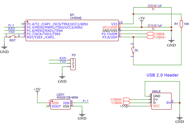
首先进行硬件的设计,电路图如下:
图片中上方是一个 CH554 的最小电路图,他是WCH 出品的一款兼容MCS51 指令集的增强型E8051内核单片机。带有256 字节内部iRAM,可以用于快速数据暂存以及堆栈;1KB 片内xRAM,可以用于大量数据暂存以及DMA直接内存存取。16KB 容量的可多次编程的非易失存储器ROM,可以全部用于程序存储空间;或者可以分为14KB 程序存储区和2KB引导代码BootLoader/ISP程序区。更特别的是其内嵌USB 控制器和USB 收发器,支持USB-Host 主机模式和USB-Device 设备模式,支持USB type-C主从检测,支持USB 2.0全速12Mbps或者低速1.5Mbps。支持最大64字节数据包,内置FIFO,支持DMA。
这里使用的型号为CH554E , MSOP-10 封装,体积非常小便于整体设备小型化。
为了调试方便,预留了P2 是UART输出。此外,还有一个 WS2812B LED 可以实现多种颜色的灯效。
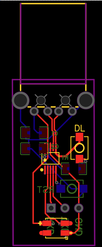
PCB 设计如下:
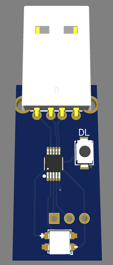
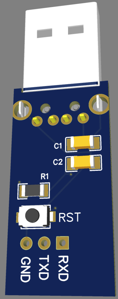
3D 预览如下
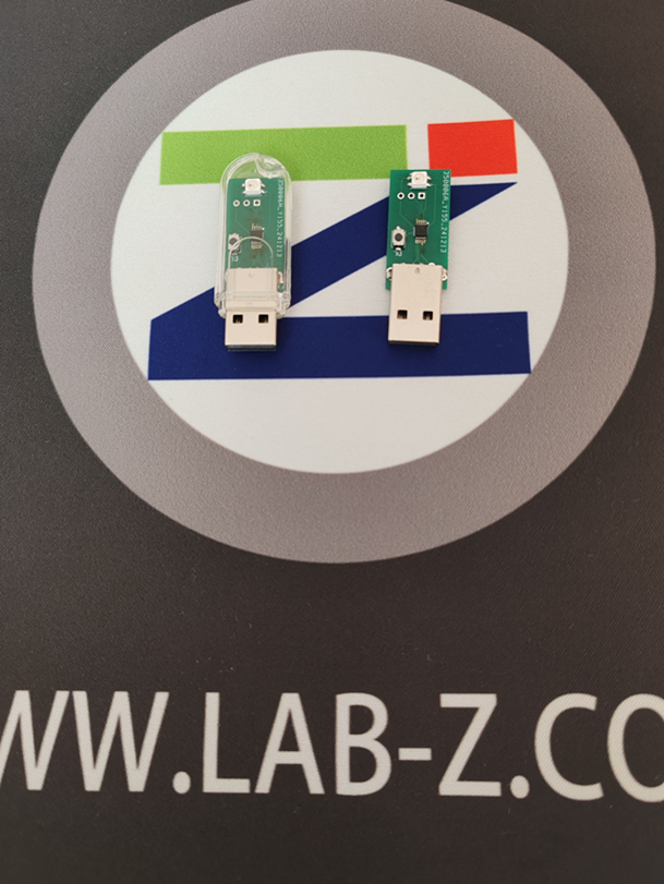
图片3 正面预览
在实际使用中,只需要焊接CH554最小系统部分即可实现USB 串口转键盘鼠标功能,其余部分可以不上件。
这次的设计尺寸是根据透明U盘外壳来的,在制作时选择 0.8mm PCB, 刚好能够放入外壳中。
硬件设计完成之后就可以进行代码的编写了。主要代码如下:
#include <WS2812.h>
#include "src/CdcHidCombo/USBCDC.h"
#include "src/CdcHidCombo/USBHIDKeyboardMouse.h"

#define NUM_LEDS 1
#define COLOR_PER_LEDS 3
#define NUM_BYTES (NUM_LEDS*COLOR_PER_LEDS)

__xdata uint8_t ledData[NUM_BYTES];

#define KeyboardReportID 0x01
#define MouseReportID    0x02
#define OnBoardLED       0x03

// Data format
// Keyboard(Total 9 bytes): 01(ReportID 01) + Keyboard data (8 Bytes)
// Mouse(Total 5 bytes): 02(ReportID 02) + Mouse Data (4 Bytes)
uint8_t recvStr[9];
uint8_t recvStrPtr = 0;
unsigned long Elsp;

void setup() {
  USBInit();
  Serial0_begin(115200);
  delay(1000);
  Serial0_print("start");
  Elsp=0;
}

void loop() {
  while (USBSerial_available()) {
    uint8_t serialChar = USBSerial_read();
    recvStr[recvStrPtr++] = serialChar;
    if (recvStrPtr == 10) {
      for (uint8_t i = 0; i < 9; i++) {
        Serial0_write(recvStr[i]);
      }
      if (recvStr[0] == KeyboardReportID) { // Keyboard
        USB_EP3_send(recvStr, 9);
      }
      if (recvStr[0] == MouseReportID) {
        USB_EP3_send(recvStr, 5); // Mouse
      }
      if (recvStr[0] == OnBoardLED) {
        set_pixel_for_GRB_LED(ledData, 0, recvStr[0], recvStr[1], recvStr[2]);
        neopixel_show_P1_5(ledData, NUM_BYTES);
      }
      recvStrPtr = 0;
    }
    Elsp=millis();
  }
  // If there is no data in 100ms, clear the receive buffer
  if (millis()-Elsp>100) {
      recvStrPtr = 0;
      Elsp=millis();
    }
}
每次收取10字节串口数据,如果第一字节为KeyboardReportID,那么直接将9个字节从端点3发送给主机;如果第一字节是MouseReportID,那么直接将5个字节从端点3发送给主机;如果第一字节为 OnBoardLED ,那么将后续3个字节合成为一个颜色信息,然后通过neopixel_show_P1_5() 函数将数据从 P1.5 引脚发送给WS2812。
USB 设备信息在USBconstant.c 文件中有描述。其中包含了 USB CDC 设备/USB 键盘/USB鼠标的描述符。其中的USB 键盘/USB鼠标使用端点3 OUTPUT。
对于键盘鼠标的 HID 描述符,在USBconstant.c文件的ReportDescriptor[]的结构体中。使用的是标准的键盘鼠标描述符。
键盘数据为8字节长:
Byte0 Byte1 Byte2 Byte3 Byte4 Byte5 Byte6 Byte7 特殊按键 NA 数据0 数据1 数据2 数据3 数据4 数据5
鼠标数据为4字节长:
Byte0 Byte1 Byte2 Byte3 左右中键 X轴数据 Y轴数据 滚轮数据
需要特别注意的是:键盘鼠标都是通过端点3发送给主机的,他们使用 Report ID 进行区分,在 ReportDescriptor[] 中有如下定义:
    0x09, 0x06,       // USAGE (Keyboard)
    0xa1, 0x01,       // COLLECTION (Application)
    0x85, 0x01,       //   REPORT_ID (1)
    0x05, 0x07,       //   USAGE_PAGE (Keyboard)
0x19, 0xe0,       //   USAGE_MINIMUM (Keyboard LeftControl)
…….
    0x09, 0x02,       // USAGE (Mouse)
    0xa1, 0x01,       // COLLECTION (Application)
    0x09, 0x01,       //   USAGE (Pointer)
    0xa1, 0x00,       //   COLLECTION (Physical)
    0x85, 0x02,       //   REPORT_ID (2)
    0x05, 0x09,       //     USAGE_PAGE (Button)
就是说,设备通过端点3发送给主机的数据,如果是 0x01 + 8个字节的数据,主机会当作键盘数据来处理;如果是0x02+4个字节的数据,主机则会当作鼠标数据来处理。
上面的代码中,USB串口,收到数据之后,将9字节和5字节发送给主机即可实现键盘和鼠标的操作了。
端点3的发送代码在 USB_EP3_send() 函数中,可以看到对于 CH554 来说,USB的发送操作非常明确简单,要发送的数据直接填充到Ep3Buffer[]中,然后设定 UEP3_T_LEN 寄存器要发送的数据长度,再设定 UEP3_CTRL 寄存器就完成了了发送。这对于USB初学者非常友好,代码直接对应硬件动作,通俗易懂。
  // 将所有数据放入 EP3 准备发送
  for (__data uint8_t i = 0; i < Len; i++) { // load data for upload
    Ep3Buffer[i] = Data[i];
  }

  UEP3_T_LEN = Len; // data length
  UpPoint3_Busy = 1;
  UEP3_CTRL = UEP3_CTRL & ~MASK_UEP_T_RES |
              UEP_T_RES_ACK; // upload data and respond ACK
上位机代码:
// CDC_vKBMSTest.cpp : This file contains the 'main' function. Program execution begins and ends there.
//

#include <windows.h>
#include <SetupAPI.h>
#include <tchar.h>
#include <iostream>
#include <cstring>
#include <atlstr.h>

#pragma comment(lib, "Setupapi.lib")

#define MY_USB_PID_VID	_T("VID_1209&PID_C55C")

class ComPortException : public std::exception {
public:
	ComPortException(DWORD errorCode) : errorCode(errorCode) {}

	DWORD getErrorCode() const {
		return errorCode;
	}

private:
	DWORD errorCode;
};

// 对串口portName 发送数据
// 无法打开串口返回 1
// 无法设置串口参数 2
void SendToComPort(const int port, const char* data) {
	int Result = 0;
	HANDLE hCom = INVALID_HANDLE_VALUE;
	TCHAR portName[10]; // 用于存储 "COMp" 字符串

// 将整数 p 转换为 "COMp" 字符串
#ifdef UNICODE
	swprintf(portName, 10, _T("\\\\.\\COM%d"), port);
#else
	sprintf(portName, "COM%d", port);
#endif
	try {
		// 打开串口
		hCom = CreateFile(portName,
			GENERIC_READ | GENERIC_WRITE,
			0,
			NULL,
			OPEN_EXISTING,
			0,
			NULL);

		if (hCom == INVALID_HANDLE_VALUE) {
			throw ComPortException(GetLastError());
		}

		// 设置串口参数
		DCB dcb;
		SecureZeroMemory(&dcb, sizeof(DCB));
		dcb.DCBlength = sizeof(DCB);

		if (!GetCommState(hCom, &dcb)) {
			throw ComPortException(GetLastError());
		}

		dcb.BaudRate = CBR_115200;  // 波特率
		dcb.ByteSize = 8;         // 数据位
		dcb.StopBits = ONESTOPBIT; // 停止位
		dcb.Parity = NOPARITY;    // 校验位

		if (!SetCommState(hCom, &dcb)) {
			throw ComPortException(GetLastError());
		}

		// 设置超时参数
		COMMTIMEOUTS timeouts;
		timeouts.ReadIntervalTimeout = 50;
		timeouts.ReadTotalTimeoutConstant = 50;
		timeouts.ReadTotalTimeoutMultiplier = 10;
		timeouts.WriteTotalTimeoutConstant = 50;
		timeouts.WriteTotalTimeoutMultiplier = 10;

		if (!SetCommTimeouts(hCom, &timeouts)) {
			throw ComPortException(GetLastError());
		}

		// 发送数据
		DWORD bytesWritten;
		if (!WriteFile(hCom, data, 10, &bytesWritten, NULL)) {
			std::cerr << "Failed to write to COM port." << std::endl;
		}
		else {
			std::cout << "Successfully sent data to COM port: [" << port << "]" << std::endl;
		}
		// 关闭串口
		if (hCom != INVALID_HANDLE_VALUE) {
			CloseHandle(hCom);
		}
	}
	catch (const ComPortException& ex) {
		std::cerr << "Error: " << ex.getErrorCode() << std::endl;
		if (hCom != INVALID_HANDLE_VALUE) {
			CloseHandle(hCom);
		}
	}

}

/************************************************************************/
/* 根据USB描述信息字符串中读取
/************************************************************************/
int MTGetPortFromVidPid(CString strVidPid)
{
	// 获取当前系统所有使用的设备
	int					nPort = -1;
	int					nStart = -1;
	int					nEnd = -1;
	int					i = 0;
	CString				strTemp, strName;
	DWORD				dwFlag = (DIGCF_ALLCLASSES | DIGCF_PRESENT);
	HDEVINFO			hDevInfo = INVALID_HANDLE_VALUE;
	SP_DEVINFO_DATA		sDevInfoData;
	TCHAR				szDis[2048] = { 0x00 };// 存储设备实例ID
	TCHAR				szFN[MAX_PATH] = { 0x00 };// 存储设备实例属性
	DWORD				nSize = 0;

	// 准备遍历所有设备查找USB
	hDevInfo = SetupDiGetClassDevs(NULL, L"USB", NULL, dwFlag);
	if (INVALID_HANDLE_VALUE == hDevInfo)
		goto STEP_END;

	// 开始遍历所有设备
	memset(&sDevInfoData, 0x00, sizeof(SP_DEVICE_INTERFACE_DATA));
	sDevInfoData.cbSize = sizeof(SP_DEVINFO_DATA);
	for (i = 0; SetupDiEnumDeviceInfo(hDevInfo, i, &sDevInfoData); i++)
	{
		nSize = 0;

		// 无效设备
		if (!SetupDiGetDeviceInstanceId(hDevInfo, &sDevInfoData, szDis, sizeof(szDis), &nSize))
			goto STEP_END;

		// 根据设备信息寻找VID PID一致的设备
		strTemp.Format(_T("%s"), szDis);
		strTemp.MakeUpper();
		if (strTemp.Find(strVidPid, 0) == -1)
			continue;

		// 查找设备属性
		nSize = 0;
		SetupDiGetDeviceRegistryProperty(hDevInfo, &sDevInfoData,
			SPDRP_FRIENDLYNAME,
			0, (PBYTE)szFN,
			sizeof(szFN),
			&nSize);

		// "XXX Virtual Com Port (COM7)"
		strName.Format(_T("%s"), szFN);
		if (strName.IsEmpty())
			//goto STEP_END;
			continue;

		// 寻找串口信息
		nStart = strName.Find(_T("(COM"), 0);
		nEnd = strName.Find(_T(")"), 0);
		if (nStart == -1 || nEnd == -1)
			//goto STEP_END;
			continue;

		strTemp = strName.Mid(nStart + 4, nEnd - nStart - 2);
		nPort = _ttoi(strTemp);

	}
STEP_END:

	// 关闭设备信息集句柄
	if (hDevInfo != INVALID_HANDLE_VALUE)
	{
		SetupDiDestroyDeviceInfoList(hDevInfo);
		hDevInfo = INVALID_HANDLE_VALUE;
	}

	return nPort;
}

int main()
{
	int Port;
	char Data[10];
	printf("Virutal KB MS Test\n");
	Port = MTGetPortFromVidPid(MY_USB_PID_VID);
	if (Port == -1) {
		printf("No device is found\n");
		goto EndProgram;
	}
	else {
		printf("Found COM%d\n",Port);
	}
	Sleep(5000);

	// 测试鼠标移动
	memset(Data,0,sizeof(Data));
	Data[0] = 2; // 鼠标
	Data[2] = 50;
	SendToComPort(Port,(char *)&Data);
	Sleep(300);
	Data[2] = 0; Data[3] = 50;
	SendToComPort(Port, (char*)&Data);
	Sleep(300);
	Data[2] = -50; Data[3] = 0x00;
	SendToComPort(Port, (char*)&Data);
	Sleep(300);
	Data[2] = 0; Data[3] = -50;
	SendToComPort(Port, (char*)&Data);
	Sleep(300);

	// 测试键盘数据
	memset(Data, 0, sizeof(Data));
	Data[0] = 1; // 键盘
	// 发送GUI信息
	Data[1] = 0x08;
	SendToComPort(Port, (char*)&Data);
	Sleep(1000);
	memset(Data, 0, sizeof(Data));
	Data[0] = 1; // 键盘
	SendToComPort(Port, (char*)&Data);
	Sleep(300);

	// 测试键盘数据
	memset(Data, 0, sizeof(Data));
	Data[0] = 1; // 键盘
	// 发送按键信息
	Data[2] = 0x04;
	Data[3] = 0x0F; //'l'
	Data[4] = 0x04; //'a '
	Data[5] = 0x05; //'b'
	Data[6] = 0x1d; //'z'
	SendToComPort(Port, (char*)&Data);
	Sleep(300);
	memset(Data, 0, sizeof(Data));
	Data[0] = 1; // 键盘
	// 抬起按键
	SendToComPort(Port, (char*)&Data);
	Sleep(300);


	// 测试LED
	memset(Data, 0, sizeof(Data));
	Data[0] = 3; // LED
	Data[1] = 0xFF;
	SendToComPort(Port, (char*)&Data);
	Sleep(500);
	memset(Data, 0, sizeof(Data));
	Data[0] = 3; // LED
	Data[2] = 0xFF;
	SendToComPort(Port, (char*)&Data);
	Sleep(500);
	memset(Data, 0, sizeof(Data));
	Data[0] = 3; // LED
	Data[3] = 0xFF;
	SendToComPort(Port, (char*)&Data);
	Sleep(500);
	memset(Data, 0, sizeof(Data));
	Data[0] = 3; // LED
	SendToComPort(Port, (char*)&Data);
	Sleep(500);

EndProgram:
	printf("End\n");
}
工作的测试视频在
电路图:
Arduino代码:
VC2019工程