取蓝牙键盘输入
Arduino 可以使用键盘作为输入设备,最常见的是下面2种接口的键盘:
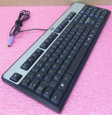
- PS2 接口的键盘。缺点是这种接口键盘市面上非常少见
- USB 键盘。这种键盘非常常见,为了在 Arduino 上使用,可以使用 USB Host Shield,缺点是占用SPI接口和多个GPIO;或者使用 CH9325 这种USB 转串口的芯片,这个方案的缺点是可能存在兼容性问题。
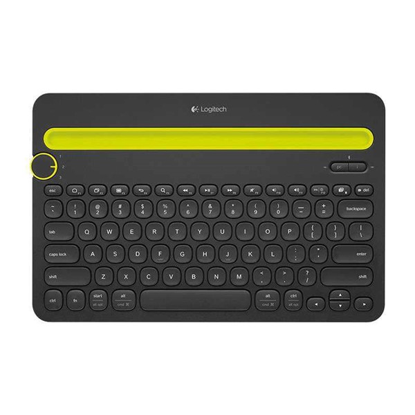
这次介绍的是ESP32 Arduino 直接读取蓝牙键盘的输入。特别需要注意的是蓝牙键盘有两种,Classical 和 BLE。我测试过罗技的 K480 是Classical蓝牙键盘:
还有苹果的A2449键盘,同样也是Classical 键盘。
IDF 提供了一个读取 Classical 键盘输入的示例,但是经过我的测试该代码无法正常工作。
这次介绍的代码只适用于 BLE 键盘,我入手的是雷柏 x220t 键鼠套装。这个键盘支持三种模式:2.4G、Classical 蓝牙和 BLE 蓝牙。

代码来自 https://github.com/esp32beans/BLE_HID_Client
/** NimBLE_Server Demo:
 *
 *  Demonstrates many of the available features of the NimBLE client library.
 *
 *  Created: on March 24 2020
 *      Author: H2zero
 *
*/

/*
 * This program is based on https://github.com/h2zero/NimBLE-Arduino/tree/master/examples/NimBLE_Client.
 * My changes are covered by the MIT license.
 */

/*
 * MIT License
 *
 * Copyright (c) 2022 esp32beans@gmail.com
 *
 * Permission is hereby granted, free of charge, to any person obtaining a copy
 * of this software and associated documentation files (the "Software"), to deal
 * in the Software without restriction, including without limitation the rights
 * to use, copy, modify, merge, publish, distribute, sublicense, and/or sell
 * copies of the Software, and to permit persons to whom the Software is
 * furnished to do so, subject to the following conditions:
 *
 * The above copyright notice and this permission notice shall be included in all
 * copies or substantial portions of the Software.
 *
 * THE SOFTWARE IS PROVIDED "AS IS", WITHOUT WARRANTY OF ANY KIND, EXPRESS OR
 * IMPLIED, INCLUDING BUT NOT LIMITED TO THE WARRANTIES OF MERCHANTABILITY,
 * FITNESS FOR A PARTICULAR PURPOSE AND NONINFRINGEMENT. IN NO EVENT SHALL THE
 * AUTHORS OR COPYRIGHT HOLDERS BE LIABLE FOR ANY CLAIM, DAMAGES OR OTHER
 * LIABILITY, WHETHER IN AN ACTION OF CONTRACT, TORT OR OTHERWISE, ARISING FROM,
 * OUT OF OR IN CONNECTION WITH THE SOFTWARE OR THE USE OR OTHER DEALINGS IN THE
 * SOFTWARE.
 */

// Install NimBLE-Arduino by h2zero using the IDE library manager.
#include <NimBLEDevice.h>

const char HID_SERVICE[] = "1812";
const char HID_INFORMATION[] = "2A4A";
const char HID_REPORT_MAP[] = "2A4B";
const char HID_CONTROL_POINT[] = "2A4C";
const char HID_REPORT_DATA[] = "2A4D";

void scanEndedCB(NimBLEScanResults results);

static NimBLEAdvertisedDevice* advDevice;

static bool doConnect = false;
static uint32_t scanTime = 0; /** 0 = scan forever */


/**  None of these are required as they will be handled by the library with defaults. **
 **                       Remove as you see fit for your needs                        */
class ClientCallbacks : public NimBLEClientCallbacks {
  void onConnect(NimBLEClient* pClient) {
    Serial.println("Connected");
    /** After connection we should change the parameters if we don't need fast response times.
     *  These settings are 150ms interval, 0 latency, 450ms timout.
     *  Timeout should be a multiple of the interval, minimum is 100ms.
     *  I find a multiple of 3-5 * the interval works best for quick response/reconnect.
     *  Min interval: 120 * 1.25ms = 150, Max interval: 120 * 1.25ms = 150, 0 latency, 60 * 10ms = 600ms timeout
     */
    pClient->updateConnParams(120,120,0,60);
  };

  void onDisconnect(NimBLEClient* pClient) {
    Serial.print(pClient->getPeerAddress().toString().c_str());
    Serial.println(" Disconnected - Starting scan");
    NimBLEDevice::getScan()->start(scanTime, scanEndedCB);
  };

  /** Called when the peripheral requests a change to the connection parameters.
   *  Return true to accept and apply them or false to reject and keep
   *  the currently used parameters. Default will return true.
   */
  bool onConnParamsUpdateRequest(NimBLEClient* pClient, const ble_gap_upd_params* params) {
    // Failing to accepts parameters may result in the remote device
    // disconnecting.
    return true;
  };

  /********************* Security handled here **********************
   ****** Note: these are the same return values as defaults ********/
  uint32_t onPassKeyRequest(){
    Serial.println("Client Passkey Request");
    /** return the passkey to send to the server */
    return 123456;
  };

  bool onConfirmPIN(uint32_t pass_key){
    Serial.print("The passkey YES/NO number: ");
    Serial.println(pass_key);
    /** Return false if passkeys don't match. */
    return true;
  };

  /** Pairing process complete, we can check the results in ble_gap_conn_desc */
  void onAuthenticationComplete(ble_gap_conn_desc* desc){
    if(!desc->sec_state.encrypted) {
      Serial.println("Encrypt connection failed - disconnecting");
      /** Find the client with the connection handle provided in desc */
      NimBLEDevice::getClientByID(desc->conn_handle)->disconnect();
      return;
    }
  };
};

/** Define a class to handle the callbacks when advertisments are received */
class AdvertisedDeviceCallbacks: public NimBLEAdvertisedDeviceCallbacks {

  void onResult(NimBLEAdvertisedDevice* advertisedDevice) {
    if ((advertisedDevice->getAdvType() == BLE_HCI_ADV_TYPE_ADV_DIRECT_IND_HD)
        || (advertisedDevice->getAdvType() == BLE_HCI_ADV_TYPE_ADV_DIRECT_IND_LD)
        || (advertisedDevice->haveServiceUUID() && advertisedDevice->isAdvertisingService(NimBLEUUID(HID_SERVICE))))
    {
      Serial.print("Advertised HID Device found: ");
      Serial.println(advertisedDevice->toString().c_str());

      /** stop scan before connecting */
      NimBLEDevice::getScan()->stop();
      /** Save the device reference in a global for the client to use*/
      advDevice = advertisedDevice;
      /** Ready to connect now */
      doConnect = true;
    }
  };
};


/** Notification / Indication receiving handler callback */
// Notification from 4c:75:25:xx:yy:zz: Service = 0x1812, Characteristic = 0x2a4d, Value = 1,0,0,0,0,
void notifyCB(NimBLERemoteCharacteristic* pRemoteCharacteristic, uint8_t* pData, size_t length, bool isNotify){
  std::string str = (isNotify == true) ? "Notification" : "Indication";
  str += " from ";
  /** NimBLEAddress and NimBLEUUID have std::string operators */
  str += std::string(pRemoteCharacteristic->getRemoteService()->getClient()->getPeerAddress());
  str += ": Service = " + std::string(pRemoteCharacteristic->getRemoteService()->getUUID());
  str += ", Characteristic = " + std::string(pRemoteCharacteristic->getUUID());
  str += ", Value = ";
  Serial.print(str.c_str());
  for (size_t i = 0; i < length; i++) {
    Serial.print(pData[i], HEX);
    Serial.print(',');
  }
  Serial.print(' ');
  if (length == 6) {
    // BLE Trackball Mouse from Amazon returns 6 bytes per HID report
    Serial.printf("buttons: %02x, x: %d, y: %d, wheel: %d",
        pData[0], *(int16_t *)&pData[1], *(int16_t *)&pData[3], (int8_t)pData[5]);
  }
  else if (length == 5) {
    // https://github.com/wakwak-koba/ESP32-NimBLE-Mouse
    // returns 5 bytes per HID report
    Serial.printf("buttons: %02x, x: %d, y: %d, wheel: %d hwheel: %d",
        pData[0], (int8_t)pData[1], (int8_t)pData[2], (int8_t)pData[3], (int8_t)pData[4]);
  }
  Serial.println();
}

/** Callback to process the results of the last scan or restart it */
void scanEndedCB(NimBLEScanResults results){
  Serial.println("Scan Ended");
}


/** Create a single global instance of the callback class to be used by all clients */
static ClientCallbacks clientCB;


/** Handles the provisioning of clients and connects / interfaces with the server */
bool connectToServer()
{
  NimBLEClient* pClient = nullptr;

  /** Check if we have a client we should reuse first **/
  if(NimBLEDevice::getClientListSize()) {
    /** Special case when we already know this device, we send false as the
     *  second argument in connect() to prevent refreshing the service database.
     *  This saves considerable time and power.
     */
    pClient = NimBLEDevice::getClientByPeerAddress(advDevice->getAddress());
    if(pClient){
      if(!pClient->connect(advDevice, false)) {
        Serial.println("Reconnect failed");
        return false;
      }
      Serial.println("Reconnected client");
    }
    /** We don't already have a client that knows this device,
     *  we will check for a client that is disconnected that we can use.
     */
    else {
      pClient = NimBLEDevice::getDisconnectedClient();
    }
  }

  /** No client to reuse? Create a new one. */
  if(!pClient) {
    if(NimBLEDevice::getClientListSize() >= NIMBLE_MAX_CONNECTIONS) {
      Serial.println("Max clients reached - no more connections available");
      return false;
    }

    pClient = NimBLEDevice::createClient();

    Serial.println("New client created");

    pClient->setClientCallbacks(&clientCB, false);
    /** Set initial connection parameters: These settings are 15ms interval, 0 latency, 120ms timout.
     *  These settings are safe for 3 clients to connect reliably, can go faster if you have less
     *  connections. Timeout should be a multiple of the interval, minimum is 100ms.
     *  Min interval: 12 * 1.25ms = 15, Max interval: 12 * 1.25ms = 15, 0 latency, 51 * 10ms = 510ms timeout
     */
    pClient->setConnectionParams(12,12,0,51);
    /** Set how long we are willing to wait for the connection to complete (seconds), default is 30. */
    pClient->setConnectTimeout(5);


    if (!pClient->connect(advDevice)) {
      /** Created a client but failed to connect, don't need to keep it as it has no data */
      NimBLEDevice::deleteClient(pClient);
      Serial.println("Failed to connect, deleted client");
      return false;
    }
  }

  if(!pClient->isConnected()) {
    if (!pClient->connect(advDevice)) {
      Serial.println("Failed to connect");
      return false;
    }
  }

  Serial.print("Connected to: ");
  Serial.println(pClient->getPeerAddress().toString().c_str());
  Serial.print("RSSI: ");
  Serial.println(pClient->getRssi());

  /** Now we can read/write/subscribe the charateristics of the services we are interested in */
  NimBLERemoteService* pSvc = nullptr;
  NimBLERemoteCharacteristic* pChr = nullptr;
  NimBLERemoteDescriptor* pDsc = nullptr;

  pSvc = pClient->getService(HID_SERVICE);
  if(pSvc) {     /** make sure it's not null */
    // This returns the HID report descriptor like this
    // HID_REPORT_MAP 0x2a4b Value: 5,1,9,2,A1,1,9,1,A1,0,5,9,19,1,29,5,15,0,25,1,75,1,
    // Copy and paste the value digits to http://eleccelerator.com/usbdescreqparser/
    // to see the decoded report descriptor.
    pChr = pSvc->getCharacteristic(HID_REPORT_MAP);
    if(pChr) {     /** make sure it's not null */
      Serial.print("HID_REPORT_MAP ");
      if(pChr->canRead()) {
        std::string value = pChr->readValue();
        Serial.print(pChr->getUUID().toString().c_str());
        Serial.print(" Value: ");
        uint8_t *p = (uint8_t *)value.data();
        for (size_t i = 0; i < value.length(); i++) {
          Serial.print(p[i], HEX);
          Serial.print(',');
        }
        Serial.println();
      }
    }
    else {
      Serial.println("HID REPORT MAP char not found.");
    }

    // Subscribe to characteristics HID_REPORT_DATA.
    // One real device reports 2 with the same UUID but
    // different handles. Using getCharacteristic() results
    // in subscribing to only one.
    std::vector<NimBLERemoteCharacteristic*>*charvector;
    charvector = pSvc->getCharacteristics(true);
    for (auto &it: *charvector) {
      if (it->getUUID() == NimBLEUUID(HID_REPORT_DATA)) {
        Serial.println(it->toString().c_str());
        if (it->canNotify()) {
          if(!it->subscribe(true, notifyCB)) {
            /** Disconnect if subscribe failed */
            Serial.println("subscribe notification failed");
            pClient->disconnect();
            return false;
          }
        }
      }
    }

  }
  Serial.println("Done with this device!");
  return true;
}

void setup ()
{
  Serial.begin(115200);

  Serial.println("Starting NimBLE HID Client");
  /** Initialize NimBLE, no device name spcified as we are not advertising */
  NimBLEDevice::init("");

  /** Set the IO capabilities of the device, each option will trigger a different pairing method.
   *  BLE_HS_IO_KEYBOARD_ONLY    - Passkey pairing
   *  BLE_HS_IO_DISPLAY_YESNO   - Numeric comparison pairing
   *  BLE_HS_IO_NO_INPUT_OUTPUT - DEFAULT setting - just works pairing
   */
  //NimBLEDevice::setSecurityIOCap(BLE_HS_IO_KEYBOARD_ONLY); // use passkey
  //NimBLEDevice::setSecurityIOCap(BLE_HS_IO_DISPLAY_YESNO); //use numeric comparison

  /** 2 different ways to set security - both calls achieve the same result.
   *  no bonding, no man in the middle protection, secure connections.
   *
   *  These are the default values, only shown here for demonstration.
   */
  NimBLEDevice::setSecurityAuth(true, false, true);
  //NimBLEDevice::setSecurityAuth(/*BLE_SM_PAIR_AUTHREQ_BOND | BLE_SM_PAIR_AUTHREQ_MITM |*/ BLE_SM_PAIR_AUTHREQ_SC);

  /** Optional: set the transmit power, default is 3db */
  NimBLEDevice::setPower(ESP_PWR_LVL_P9); /** +9db */

  /** Optional: set any devices you don't want to get advertisments from */
  // NimBLEDevice::addIgnored(NimBLEAddress ("aa:bb:cc:dd:ee:ff"));

  /** create new scan */
  NimBLEScan* pScan = NimBLEDevice::getScan();

  /** create a callback that gets called when advertisers are found */
  pScan->setAdvertisedDeviceCallbacks(new AdvertisedDeviceCallbacks());

  /** Set scan interval (how often) and window (how long) in milliseconds */
  pScan->setInterval(45);
  pScan->setWindow(15);

  /** Active scan will gather scan response data from advertisers
   *  but will use more energy from both devices
   */
  pScan->setActiveScan(true);
  /** Start scanning for advertisers for the scan time specified (in seconds) 0 = forever
   *  Optional callback for when scanning stops.
   */
  pScan->start(scanTime, scanEndedCB);
}


void loop ()
{
  /** Loop here until we find a device we want to connect to */
  if (!doConnect) return;

  doConnect = false;

  /** Found a device we want to connect to, do it now */
  if(connectToServer()) {
    Serial.println("Success! we should now be getting notifications!");
  } else {
    Serial.println("Failed to connect, starting scan");
    NimBLEDevice::getScan()->start(scanTime,scanEndedCB);
  }
}
烧录完成后,切换键盘到蓝牙模式,然后ESP32 S3 会和键盘配对,之后就可以读取到按键信息了:
Starting NimBLE HID Client
Advertised HID Device found: Name: RAPOO BT4.0 KB, Address: b4:ee:25:f3:86:99, appearance: 961, serviceUUID: 0x1812
Scan Ended
New client created
Connected
Connected to: b4:ee:25:f3:86:99
RSSI: -64
HID_REPORT_MAP 0x2a4b Value:
Done with this device!
Success! we should now be getting notifications!
b4:ee:25:f3:86:99 Disconnected - Starting scan
Advertised HID Device found: Name: RAPOO BT4.0 KB, Address: b4:ee:25:f3:86:99, appearance: 961, serviceUUID: 0x1812
Scan Ended
Connected
Reconnected client
Connected to: b4:ee:25:f3:86:99
RSSI: -43
HID_REPORT_MAP 0x2a4b Value:
Done with this device!
Success! we should now be getting notifications!
b4:ee:25:f3:86:99 Disconnected - Starting scan
Advertised HID Device found: Name: RAPOO BT4.0 KB, Address: b4:ee:25:f3:86:99, appearance: 961, serviceUUID: 0x1812
Scan Ended
Connected
Reconnected client
Connected to: b4:ee:25:f3:86:99
RSSI: -42
HID_REPORT_MAP 0x2a4b Value: 5,1,9,6,A1,1,85,1,5,7,19,E0,29,E7,15,0,25,1,75,1,95,8,81,2,95,1,75,8,81,3,95,5,75,1,5,8,19,1,29,5,91,2,95,1,75,3,91,3,95,6,75,8,15,0,26,FF,0,5,7,19,0,29,FF,81,0,C0,5,C,9,1,A1,1,85,2,15,0,25,1,75,1,95,1E,A,24,2,A,25,2,A,26,2,A,27,2,A,21,2,A,2A,2,A,23,2,A,8A,1,9,E2,9,EA,9,E9,9,CD,9,B7,9,B6,9,B5,A,83,1,A,94,1,A,92,1,A,9,2,9,B2,9,B3,9,B4,9,8D,9,4,9,30,A,7,3,A,A,3,A,B,3,A,B1,1,9,B8,81,2,95,1,75,2,81,3,C0,
Characteristic: uuid: 0x2a4d, handle: 27 0x001b, props:  0x1a
Characteristic: uuid: 0x2a4d, handle: 31 0x001f, props:  0x1a
Characteristic: uuid: 0x2a4d, handle: 35 0x0023, props:  0x0e
Done with this device!
Success! we should now be getting notifications!
Notification from b4:ee:25:f3:86:99: Service = 0x1812, Characteristic = 0x2a4d, Value = 0,0,14,2B,0,0,0,0,
Notification from b4:ee:25:f3:86:99: Service = 0x1812, Characteristic = 0x2a4d, Value = 0,0,2B,0,0,0,0,0,
Notification from b4:ee:25:f3:86:99: Service = 0x1812, Characteristic = 0x2a4d, Value = 0,0,0,0,0,0,0,0,
Notification from b4:ee:25:f3:86:99: Service = 0x1812, Characteristic = 0x2a4d, Value = 0,0,14,0,0,0,0,0,
Notification from b4:ee:25:f3:86:99: Service = 0x1812, Characteristic = 0x2a4d, Value = 0,0,0,0,0,0,0,0,
Notification from b4:ee:25:f3:86:99: Service = 0x1812, Characteristic = 0x2a4d, Value = 0,0,2C,0,0,0,0,0,