一个 C# 编写的 HTTP Server 的项目,足够简单,很容易根据自身需要扩展和修改。
我用这个创建了一个 Web Server ,然后用户通过浏览器访问Server 和一个 Arduino 设计进行通讯。
一个 C# 编写的 HTTP Server 的项目,足够简单,很容易根据自身需要扩展和修改。
我用这个创建了一个 Web Server ,然后用户通过浏览器访问Server 和一个 Arduino 设计进行通讯。
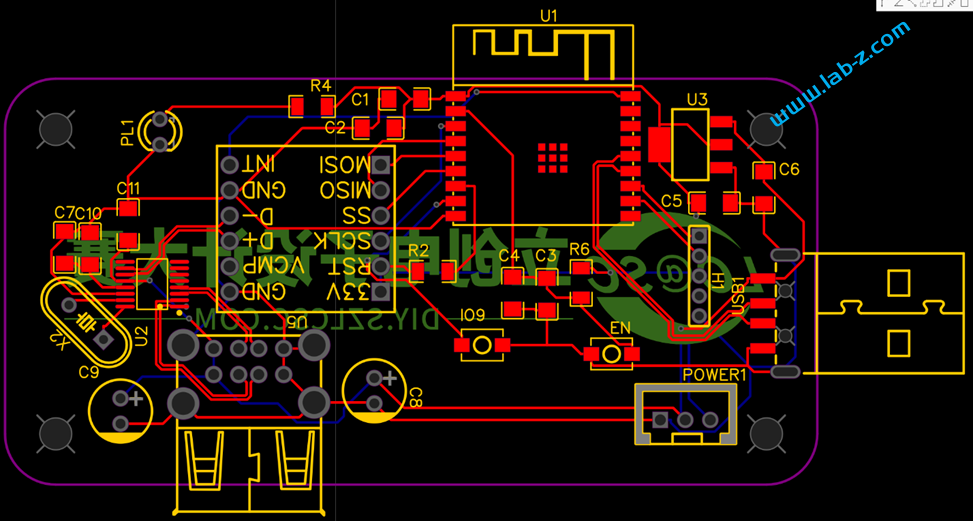
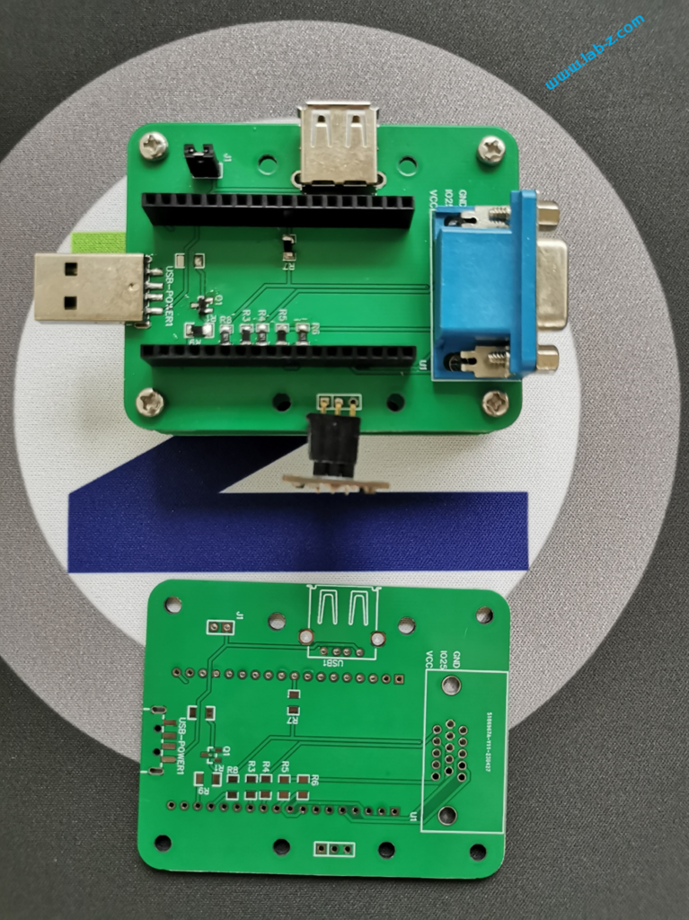
这次带来的作品是 DFRobot Beetle ESP32-C3的扩展版,通过这个扩展版能够让 Beetle ESP32-C3 取得 USB 键盘鼠标这种 HID 设备的输入数据。
这个扩展版的核心是 WCH 出品的CH9350芯片,CH9350是USB键盘鼠标转串口通讯控制芯片。就是说USB 键盘鼠标连接到这个芯片之后,数据会转化为串口输出。关于这个芯片的功能介绍如下:
电路图设计如下:
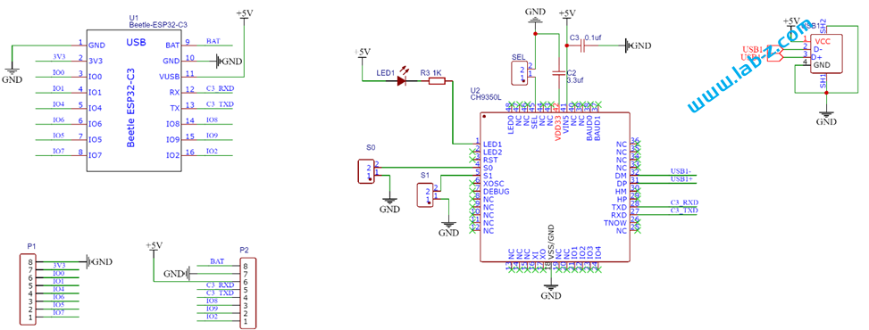
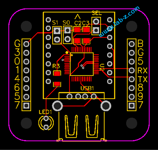
从DataSheet可以知道,芯片支持 3.3V h和5V供电,为了方便电路设计这里我们直接使用5V供电。PCB 设计如下:
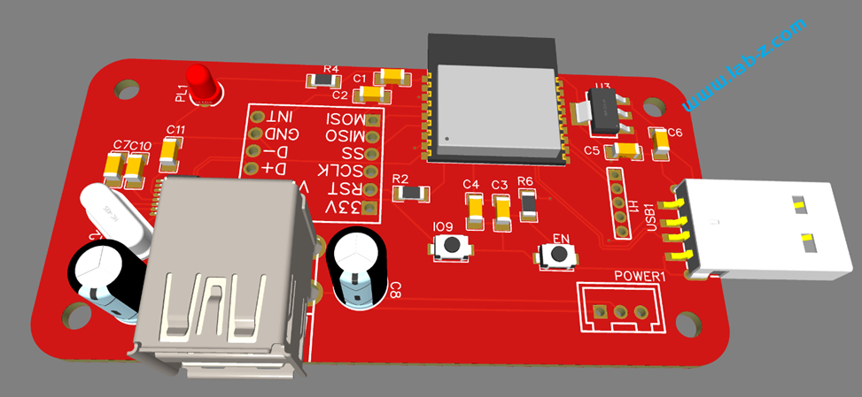
3D渲染结果如下:
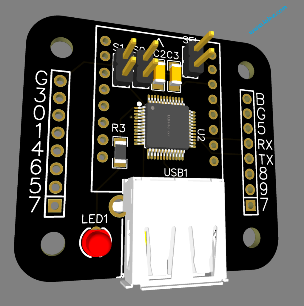
黑色PCB 风格非常接近DFRobot
为了Beetle 配合板子只使用了一个 USB 母头,实际芯片同时支持2个USB接口,让客户可以同时使用键盘和鼠标。
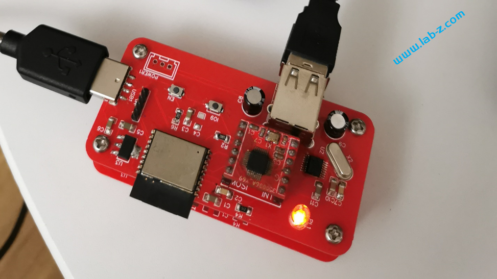
下面带来一个USB键盘转蓝牙例子,展示这个板子的能力。
从原理上来说,首先使用 CH9350取得鼠标数据,之后通过 Beetle ESP32-C3 的蓝牙功能将这个数据发送出去。
#include <Arduino.h>
#include <BleKeyboard.h>

BleKeyboard bleKeyboard;

#define DEBUGMODE 1

void setup() {
  Serial.begin(115200);
  Serial1.begin(115200, SERIAL_8N1, RX, TX);

  bleKeyboard.begin();

}

void loop() {
  while (Serial.available()) {
    char c = Serial.read();
    if (c == '1') {
      Serial.println("get1");
    }
    if (c == '3') {
      ESP.restart();
    }
  }

  //根据 CH9350 Spec 每次最多输出 72Bytes
  byte Data[72];
  unsigned int CounterLast = Serial1.available();
  unsigned int CounterCurrent = 0;


  // 如果当前串口有数据
  if (CounterLast != 0) {
    // 进行简单测试,如果当前还在传输数据那么持续接收
    while (CounterCurrent != CounterLast) {
      CounterLast = Serial1.available();
      delayMicroseconds(500);
      CounterCurrent = Serial1.available();
    }
  }

  if (CounterCurrent > 0) {
    // 一次性将数据收取下来
    Serial1.readBytes(Data, CounterCurrent);
    unsigned int i = 0;
    unsigned int Length;
    while (i < CounterCurrent) {
      // 识别帧头
      if ((Data[i] == 0x57) && (Data[i + 1] == 0xAB)) {
        // 有效键值帧
        if (Data[i + 2] == 0x88) {
          // 获得数据长度
          Length = Data[i + 3];
          if (DEBUGMODE) {
            //Serial.print("Ln:");Serial.print(Length);
            for (int j = 1; j < Length + 1; j++) {
              if (Data[i + 3  + j] < 16) {
                Serial.print("0");
              }
              Serial.print(Data[i + 3  + j], HEX);
              Serial.print(" ");
            }
            Serial.println(" ");
          }

          //如果是键盘
          if (Data[i + 4] == 0x10) {
            if (DEBUGMODE) {
              Serial.print("Key");
              for (int j = 1; j < Length + 1; j++) {
                Serial.print(Data[i + 3  + j], HEX);
                Serial.print(" ");
              }
              Serial.println(" ");
            }

            //判断为Dostyle键盘
            if (Data[i + 3  + 1] == 0x10) {
              if (bleKeyboard.isConnected() == true) {
                bleKeyboard.sendReport((KeyReport*)(&Data[i + 3  + 2]));
              }
            }
          }
          i = i + 3 + Length;
        } else if (Data[i + 2] == 0x82) {
          i = i + 3; // 跳过
        }
      }
      i++;
    } // while (i < Counter)
  }

}
首先,调用了 ESP32 的 BLE 键盘库(第三方),创建一个蓝牙键盘;之后就是分析串口数据。CH9350 能够获得USB 键盘鼠标数据,但是获得这个数据每家会有差别。正确的做法是使用工具(USBlyzer)读取键盘鼠标数据,然后编写分析代码。或者是使用工具读取这个设备的 HID Report Descriptor。再进一步解释就是,例如:市面上有2中鼠标,他们发送出来的数据格式可能是:
A鼠标:
Byte0: Button
Byte1: X
Byte2: Y
Byte3: Wheel
B鼠标:
Byte0: Button
Byte1: X 低8位
Byte2: X 高8位
Byte3: X 低8位
Byte4: X 高8位
Byte5: Wheel
具体的格式数据是设备通过HID Report Descriptor报告给系统的,而对于我们来说只能通过人工识别然后在代码中分析的方式来实现解析。相比USB鼠标,键盘的情况要好得多,通常都是使用8 Bytes 来报告按键信息。我这次测试使用的是一款机械键盘,使用的同样是 8 Bytes的格式,因此代码中直接将对应的数据以KeyReport结构体直接发送出去。
if (bleKeyboard.isConnected() == true) {
                bleKeyboard.sendReport((KeyReport*)(&Data[i + 3  + 2]));
 }
本文提到的电路图和PCB:
本文提到的完整代码:
本文使用的库:
上个月edk2 202308 正式发布在:
https://github.com/tianocore/edk2/releases/tag/edk2-stable202308
从 History 来看,改动并不大:
和之前类似,这里放上一个完整版,补全了所有的三方库,大小是107MB 左右。
https://pan.baidu.com/s/1rQf19nHbpxDdwB5DJkVi0w?pwd=LABZ
提取码: LABZ
此外,为了方便初学者,这里提供一个配置好的 Win10+VS2019 EDK2 环境,导入即可上手:
https://pan.baidu.com/s/1B9aFEcRur8xY4g1X6Fdgcg?pwd=labz
提取码: labz
这次带来的项目是一个能够将两个USB 手柄转为蓝牙手柄的项目,这样玩家可以不受距离的限制使用手柄进行游戏。
项目基于 ESP32 C3 作为主控,使用 Max3421e 芯片作为 USB Host ,经过 WCH 的CH334 USB HUB 芯片扩展出2个USB 接口,这样就能同时连接2个USB手柄(CH334 支持一转四,因此最多同时可以连接4个USB手柄)。获得数据之后, C3 将自身模拟为USB 手柄设备,将按键数据通过蓝牙上传给主机,这样就实现了将两个USB 手柄转为蓝牙手柄。
下面首先介绍硬件设计。
完整电路图如下:
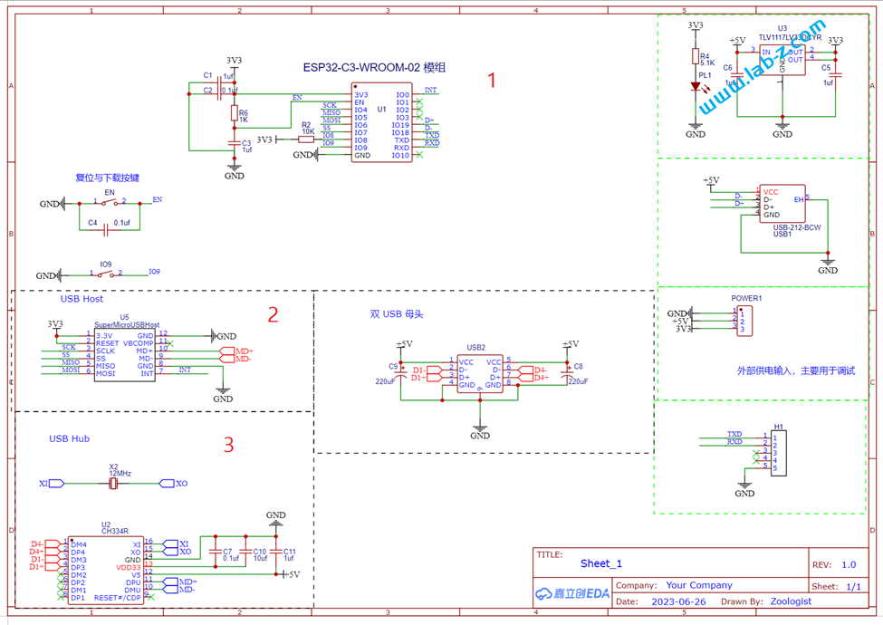
电路1 是 ESP32 C3 模块。ESP32-C3是一款安全稳定、低功耗、低成本的物联网芯片,搭载 RISC-V 32 位单核处理器,时钟频率高达 160 MHz。具有 22 个可编程 GPIO 管脚、内置 400 KB SRA、支持 2.4 GHz Wi-Fi 和 Bluetooth 5 (LE)。从图中也可以看到其所需外围元件很少,方便应用;
电路2是我们之前设计的 Super Micro USB Host,它的核心是 Max3421e 芯片,这个方案我们多次使用,是非常优秀的USB Host 方案;
电路3 是 USB Hub 部分,这里使用了CH334芯片.这款芯片符合 USB2.0 协议规范的4 端口 USB HUB 控制器芯片,上行端口支持 USB2.0高速和全速,下行端口支持 USB2.0 高速480Mbps、全速 12Mbps 和低速1.5Mbps。不但支持低成本的的 STT 模式(单个TT分时调度4个下行端口),还支持高性能的 MTT 模式 (4个TT各对应1个端口,并发处理)。需要注意的是,在此之前我实验过价格低廉的 FE1.2 芯片,但是FE1.2对 Max3421e 存在兼容性问题,无法正常工作。最终选择了CH334这个。如果有需要对 Max3421e 扩展USB 来使用的朋友,请注意USB Hub 这个坑。
上面就是这个设计最主要的三个部分,其他的都是辅助部分。
PCB 设计如下:
3D 预览如下:
焊接安装之后如下:
硬件完成后就要开始着手软件的设计了。
中所周知,USB HID的一个特点是:无需驱动即可使用。实现这个功能的秘密在于:在开始工作后设备会对主机发送一个HID Report Descriptor。在这个 Descriptor中描述了数据格式。这样主机收到之后能够清晰的了解收到的数据包中数据的含义,比如:Report Descriptor 内容是第一个字节是按键信息,第二个字节表示 X 坐标,第三个字节表示Y坐标。这样,当主机收到 01 00 00 ,主机知道有按键按下;当主机收到 00 0A 00 ,它能够知道鼠标向右移动了10 像素。蓝牙HID 也有类似的设计,其中的Report Descriptor 在蓝牙上成为Report Map 。其中的条目定义和 USB HID 的完全相同。因此,这里我们通过很小的改动就能将USB 手柄迁移到蓝牙上,他们使用相同的 Report Descriptor也能够避免数据解析的麻烦。仍然以前面的鼠标为例,当蓝牙设备使用和USB 设备相同的Report Descriptor时,主机对于 00 0A 00 这种数据,都能解析为鼠标向右移动了10 像素。
下面是我使用的 USB 手柄的 Report Descriptor:
Interface 0 HID Report Descriptor Joystick
Item Tag (Value)	Raw Data
Usage Page (Generic Desktop)	05 01
Usage (Joystick)	09 04
Collection (Application)	A1 01
    Report ID (1)	85 01
    Collection (Logical)	A1 02
        Report Size (8)	75 08
        Report Count (4)	95 04
        Logical Minimum (0)	15 00
        Logical Maximum (255)	26 FF 00
        Physical Minimum (0)	35 00
        Physical Maximum (255)	46 FF 00
        Usage (Rz)	09 35
        Usage (Z)	09 32
        Usage (X)	09 30
        Usage (Y)	09 31
        Input (Data,Var,Abs,NWrp,Lin,Pref,NNul,Bit)	81 02
        Report Size (4)	75 04
        Report Count (1)	95 01
        Logical Maximum (7)	25 07
        Physical Maximum (315)	46 3B 01
        Unit (Eng Rot: Degree)	65 14
        Usage (Hat Switch)	09 39
        Input (Data,Var,Abs,NWrp,Lin,Pref,Null,Bit)	81 42
        Unit (None)	65 00
        Report Size (1)	75 01
        Report Count (12)	95 0C
        Logical Maximum (1)	25 01
        Physical Maximum (1)	45 01
        Usage Page (Button)	05 09
        Usage Minimum (Button 1)	19 01
        Usage Maximum (Button 12)	29 0C
        Input (Data,Var,Abs,NWrp,Lin,Pref,NNul,Bit)	81 02
        Usage Page (Vendor-Defined 1)	06 00 FF
        Report Size (1)	75 01
        Report Count (8)	95 08
        Logical Maximum (1)	25 01
        Physical Maximum (1)	45 01
        Usage (Vendor-Defined 1)	09 01
        Input (Data,Var,Abs,NWrp,Lin,Pref,NNul,Bit)	81 02
    End Collection	C0
    Collection (Logical)	A1 02
        Report Size (8)	75 08
        Report Count (4)	95 04
        Physical Maximum (255)	46 FF 00
        Logical Maximum (255)	26 FF 00
        Usage (Vendor-Defined 2)	09 02
        Output (Data,Var,Abs,NWrp,Lin,Pref,NNul,NVol,Bit)	91 02
    End Collection	C0
End Collection	C0
Usage Page (Generic Desktop)	05 01
Usage (Joystick)	09 04
Collection (Application)	A1 01
    Report ID (2)	85 02
    Collection (Logical)	A1 02
        Report Size (8)	75 08
        Report Count (4)	95 04
        Logical Minimum (0)	15 00
        Logical Maximum (255)	26 FF 00
        Physical Minimum (0)	35 00
        Physical Maximum (255)	46 FF 00
        Usage (Rz)	09 35
        Usage (Z)	09 32
        Usage (X)	09 30
        Usage (Y)	09 31
        Input (Data,Var,Abs,NWrp,Lin,Pref,NNul,Bit)	81 02
        Report Size (4)	75 04
        Report Count (1)	95 01
        Logical Maximum (7)	25 07
        Physical Maximum (315)	46 3B 01
        Unit (Eng Rot: Degree)	65 14
        Usage (Hat Switch)	09 39
        Input (Data,Var,Abs,NWrp,Lin,Pref,Null,Bit)	81 42
        Unit (None)	65 00
        Report Size (1)	75 01
        Report Count (12)	95 0C
        Logical Maximum (1)	25 01
        Physical Maximum (1)	45 01
        Usage Page (Button)	05 09
        Usage Minimum (Button 1)	19 01
上面红色标记出来的是这次使用的USB手柄的有效部分。除了红色还有黑色的字体,从实验来看,在手柄时没有使用。我们将有效部分取出,合成一个蓝牙使用的Report Map如下:
  // 1st Gamepad
  0x05, 0x01,        // Usage Page (Generic Desktop Ctrls)
  0x09, 0x04,        // Usage (Joystick)
  0xA1, 0x01,        // Collection (Application)
  0x85, 0x01,        //   Report ID (1)
  0xA1, 0x02,        //   Collection (Logical)
  0x75, 0x08,        //     Report Size (8)
  0x95, 0x04,        //     Report Count (4)
  0x15, 0x00,        //     Logical Minimum (0)
  0x26, 0xFF, 0x00,  //     Logical Maximum (255)
  0x35, 0x00,        //     Physical Minimum (0)
  0x46, 0xFF, 0x00,  //     Physical Maximum (255)
  0x09, 0x35,        //     Usage (Rz)
  0x09, 0x32,        //     Usage (Z)
  0x09, 0x30,        //     Usage (X)
  0x09, 0x31,        //     Usage (Y)
  0x81, 0x02,        //     Input (Data,Var,Abs,No Wrap,Linear,Preferred State,No Null Position)
  0x75, 0x04,        //     Report Size (4)
  0x95, 0x01,        //     Report Count (1)
  0x25, 0x07,        //     Logical Maximum (7)
  0x46, 0x3B, 0x01,  //     Physical Maximum (315)
  0x65, 0x14,        //     Unit (System: English Rotation, Length: Centimeter)
  0x09, 0x39,        //     Usage (Hat switch)
  0x81, 0x42,        //     Input (Data,Var,Abs,No Wrap,Linear,Preferred State,Null State)
  0x65, 0x00,        //     Unit (None)
  0x75, 0x01,        //     Report Size (1)
  0x95, 0x0C,        //     Report Count (12)
  0x25, 0x01,        //     Logical Maximum (1)
  0x45, 0x01,        //     Physical Maximum (1)
  0x05, 0x09,        //     Usage Page (Button)
  0x19, 0x01,        //     Usage Minimum (0x01)
  0x29, 0x0C,        //     Usage Maximum (0x0C)
  0x81, 0x02,        //     Input (Data,Var,Abs,No Wrap,Linear,Preferred State,No Null Position)
  0x06, 0x00, 0xFF,  //     Usage Page (Vendor Defined 0xFF00)
  0x75, 0x01,        //     Report Size (1)
  0x95, 0x08,        //     Report Count (8)
  0x25, 0x01,        //     Logical Maximum (1)
  0x45, 0x01,        //     Physical Maximum (1)
  0x09, 0x01,        //     Usage (0x01)
  0x81, 0x02,        //     Input (Data,Var,Abs,No Wrap,Linear,Preferred State,No Null Position)
  0xC0,              //   End Collection
  0xA1, 0x02,        //   Collection (Logical)
  0x75, 0x08,        //     Report Size (8)
  0x95, 0x04,        //     Report Count (4)
  0x46, 0xFF, 0x00,  //     Physical Maximum (255)
  0x26, 0xFF, 0x00,  //     Logical Maximum (255)
  0x09, 0x02,        //     Usage (0x02)
  0x91, 0x02,        //     Output (Data,Var,Abs,No Wrap,Linear,Preferred State,No Null Position,Non-volatile)
  0xC0,              //   End Collection
  0xC0,              // End Collection

  // 2nd Gamepad
  0x05, 0x01,        // Usage Page (Generic Desktop Ctrls)
  0x09, 0x04,        // Usage (Joystick)
  0xA1, 0x01,        // Collection (Application)
  0x85, 0x02,        //   Report ID (2)
  0xA1, 0x02,        //   Collection (Logical)
  0x75, 0x08,        //     Report Size (8)
  0x95, 0x04,        //     Report Count (4)
  0x15, 0x00,        //     Logical Minimum (0)
  0x26, 0xFF, 0x00,  //     Logical Maximum (255)
  0x35, 0x00,        //     Physical Minimum (0)
  0x46, 0xFF, 0x00,  //     Physical Maximum (255)
  0x09, 0x35,        //     Usage (Rz)
  0x09, 0x32,        //     Usage (Z)
  0x09, 0x30,        //     Usage (X)
  0x09, 0x31,        //     Usage (Y)
  0x81, 0x02,        //     Input (Data,Var,Abs,No Wrap,Linear,Preferred State,No Null Position)
  0x75, 0x04,        //     Report Size (4)
  0x95, 0x01,        //     Report Count (1)
  0x25, 0x07,        //     Logical Maximum (7)
  0x46, 0x3B, 0x01,  //     Physical Maximum (315)
  0x65, 0x14,        //     Unit (System: English Rotation, Length: Centimeter)
  0x09, 0x39,        //     Usage (Hat switch)
  0x81, 0x42,        //     Input (Data,Var,Abs,No Wrap,Linear,Preferred State,Null State)
  0x65, 0x00,        //     Unit (None)
  0x75, 0x01,        //     Report Size (1)
  0x95, 0x0C,        //     Report Count (12)
  0x25, 0x01,        //     Logical Maximum (1)
  0x45, 0x01,        //     Physical Maximum (1)
  0x05, 0x09,        //     Usage Page (Button)
  0x19, 0x01,        //     Usage Minimum (0x01)
  0x29, 0x0C,        //     Usage Maximum (0x0C)
  0x81, 0x02,        //     Input (Data,Var,Abs,No Wrap,Linear,Preferred State,No Null Position)
  0x06, 0x00, 0xFF,  //     Usage Page (Vendor Defined 0xFF00)
  0x75, 0x01,        //     Report Size (1)
  0x95, 0x08,        //     Report Count (8)
  0x25, 0x01,        //     Logical Maximum (1)
  0x45, 0x01,        //     Physical Maximum (1)
  0x09, 0x01,        //     Usage (0x01)
  0x81, 0x02,        //     Input (Data,Var,Abs,No Wrap,Linear,Preferred State,No Null Position)
  0xC0,              //   End Collection
  0xA1, 0x02,        //   Collection (Logical)
  0x75, 0x08,        //     Report Size (8)
  0x95, 0x04,        //     Report Count (4)
  0x46, 0xFF, 0x00,  //     Physical Maximum (255)
  0x26, 0xFF, 0x00,  //     Logical Maximum (255)
  0x09, 0x02,        //     Usage (0x02)
  0x91, 0x02,        //     Output (Data,Var,Abs,No Wrap,Linear,Preferred State,No Null Position,Non-volatile)
  0xC0,              //   End Collection
  0xC0,              // End Collection
可以看到,上面的 Descriptor 红色部分和其余部分的区别只是 Report ID 不同。 Report ID 是USB HID 设备用来区分功能的一个设计。例如,我们经常遇到同时带有键盘和鼠标的混合设备。通常它的Descriptor 写法就是:
Report ID 1
鼠标数据[0], 鼠标数据[1], ……鼠标数据[M-1],
Report ID 2
键盘数据[0], 键盘数据[1],……键盘数据[N-1],
当设备上有鼠标动作发生时,鼠标动作描述为 :M 长度的鼠标数据;设备对主机的报告是:
1, 鼠标数据[0], 鼠标数据[1],…… 鼠标数据[M-1]
当设备上有键盘动作发生时,键盘动作描述为 :N 长度的键盘数据;设备对主机的报告是:
2,键盘数据[0], 键盘数据[1],…… 键盘数据[N-1]
当然,你还可以继续给这个设备加入功能。比如:Report ID 3 , 键盘数据[0], 键盘数据[1],……键盘数据[P-1] 这样就又加入了一个键盘的功能(实际上这样做是有意义的,比如,通常的USB键盘数据包只有8个按键信息,如果我们同时按下9个按键就会超出它的运载能力。这就是一种“键位冲突”。如果你的设备同时声明了2个键盘,那么可以用将第九个按键的信息放置在第二个键盘的数据中发出去。如果你肯声明三个键盘设备,每个带有8个按键,理论上对于人类是完全够用的)。显而易见,通过 Report ID 主机能够分清楚当收到的数据属于哪个设备。
这次的设计,USB 手柄产生数据如下:
1, 手柄数据[0], 手柄数据[1],…… 手柄数据[M-1]
(第一个1是来自USB 手柄 Descriptor 的 Report ID 1)
我们无需解析了解每一位的含义,去掉最前面的 Report ID 然后将剩余数据转发出去即可。具体代码如下:
  if (DataBuffer[0] == 0) {
    input->setValue(&DataBuffer[2], RPT_GEMEPAD_LEN - 2);
    input->notify();
  }
  if (DataBuffer[0] == 1) {
    input2->setValue(&DataBuffer[2], RPT_GEMEPAD_LEN - 2);
    input2->notify();
  }
主机收到数据之后,能够分清楚来源,然后将数据通过蓝牙转发出去即可。完整代码如下:
#include <BLEDevice.h>
#include <BLEUtils.h>
#include <BLEServer.h>

#include "BLE2902.h"
#include "BLEHIDDevice.h"
#include "HIDTypes.h"

#include <usbhid.h>
#include <hiduniversal.h>
#include <usbhub.h>

#define DEBUGMODE 0

// Satisfy IDE, which only needs to see the include statment in the ino.
#ifdef dobogusinclude
#include <spi4teensy3.h>
#endif
#include <SPI.h>

#include "hidjoystickrptparser.h"

USB Usb;
USBHub Hub(&Usb);
HIDUniversal Hid1(&Usb);
HIDUniversal Hid2(&Usb);
JoystickEvents JoyEvents;
JoystickReportParser Joy(&JoyEvents);

BLEHIDDevice*       hid;
BLECharacteristic*  input;

BLECharacteristic*  input2;
BLECharacteristic*  output2;
bool      connected = false;


const uint8_t report[] = {
  // 1st Gamepad
  0x05, 0x01,        // Usage Page (Generic Desktop Ctrls)
  0x09, 0x04,        // Usage (Joystick)
  0xA1, 0x01,        // Collection (Application)
  0x85, 0x01,        //   Report ID (1)
  0xA1, 0x02,        //   Collection (Logical)
  0x75, 0x08,        //     Report Size (8)
  0x95, 0x04,        //     Report Count (4)
  0x15, 0x00,        //     Logical Minimum (0)
  0x26, 0xFF, 0x00,  //     Logical Maximum (255)
  0x35, 0x00,        //     Physical Minimum (0)
  0x46, 0xFF, 0x00,  //     Physical Maximum (255)
  0x09, 0x35,        //     Usage (Rz)
  0x09, 0x32,        //     Usage (Z)
  0x09, 0x30,        //     Usage (X)
  0x09, 0x31,        //     Usage (Y)
  0x81, 0x02,        //     Input (Data,Var,Abs,No Wrap,Linear,Preferred State,No Null Position)
  0x75, 0x04,        //     Report Size (4)
  0x95, 0x01,        //     Report Count (1)
  0x25, 0x07,        //     Logical Maximum (7)
  0x46, 0x3B, 0x01,  //     Physical Maximum (315)
  0x65, 0x14,        //     Unit (System: English Rotation, Length: Centimeter)
  0x09, 0x39,        //     Usage (Hat switch)
  0x81, 0x42,        //     Input (Data,Var,Abs,No Wrap,Linear,Preferred State,Null State)
  0x65, 0x00,        //     Unit (None)
  0x75, 0x01,        //     Report Size (1)
  0x95, 0x0C,        //     Report Count (12)
  0x25, 0x01,        //     Logical Maximum (1)
  0x45, 0x01,        //     Physical Maximum (1)
  0x05, 0x09,        //     Usage Page (Button)
  0x19, 0x01,        //     Usage Minimum (0x01)
  0x29, 0x0C,        //     Usage Maximum (0x0C)
  0x81, 0x02,        //     Input (Data,Var,Abs,No Wrap,Linear,Preferred State,No Null Position)
  0x06, 0x00, 0xFF,  //     Usage Page (Vendor Defined 0xFF00)
  0x75, 0x01,        //     Report Size (1)
  0x95, 0x08,        //     Report Count (8)
  0x25, 0x01,        //     Logical Maximum (1)
  0x45, 0x01,        //     Physical Maximum (1)
  0x09, 0x01,        //     Usage (0x01)
  0x81, 0x02,        //     Input (Data,Var,Abs,No Wrap,Linear,Preferred State,No Null Position)
  0xC0,              //   End Collection
  0xA1, 0x02,        //   Collection (Logical)
  0x75, 0x08,        //     Report Size (8)
  0x95, 0x04,        //     Report Count (4)
  0x46, 0xFF, 0x00,  //     Physical Maximum (255)
  0x26, 0xFF, 0x00,  //     Logical Maximum (255)
  0x09, 0x02,        //     Usage (0x02)
  0x91, 0x02,        //     Output (Data,Var,Abs,No Wrap,Linear,Preferred State,No Null Position,Non-volatile)
  0xC0,              //   End Collection
  0xC0,              // End Collection


  // 2nd Gamepad
  0x05, 0x01,        // Usage Page (Generic Desktop Ctrls)
  0x09, 0x04,        // Usage (Joystick)
  0xA1, 0x01,        // Collection (Application)
  0x85, 0x02,        //   Report ID (2)
  0xA1, 0x02,        //   Collection (Logical)
  0x75, 0x08,        //     Report Size (8)
  0x95, 0x04,        //     Report Count (4)
  0x15, 0x00,        //     Logical Minimum (0)
  0x26, 0xFF, 0x00,  //     Logical Maximum (255)
  0x35, 0x00,        //     Physical Minimum (0)
  0x46, 0xFF, 0x00,  //     Physical Maximum (255)
  0x09, 0x35,        //     Usage (Rz)
  0x09, 0x32,        //     Usage (Z)
  0x09, 0x30,        //     Usage (X)
  0x09, 0x31,        //     Usage (Y)
  0x81, 0x02,        //     Input (Data,Var,Abs,No Wrap,Linear,Preferred State,No Null Position)
  0x75, 0x04,        //     Report Size (4)
  0x95, 0x01,        //     Report Count (1)
  0x25, 0x07,        //     Logical Maximum (7)
  0x46, 0x3B, 0x01,  //     Physical Maximum (315)
  0x65, 0x14,        //     Unit (System: English Rotation, Length: Centimeter)
  0x09, 0x39,        //     Usage (Hat switch)
  0x81, 0x42,        //     Input (Data,Var,Abs,No Wrap,Linear,Preferred State,Null State)
  0x65, 0x00,        //     Unit (None)
  0x75, 0x01,        //     Report Size (1)
  0x95, 0x0C,        //     Report Count (12)
  0x25, 0x01,        //     Logical Maximum (1)
  0x45, 0x01,        //     Physical Maximum (1)
  0x05, 0x09,        //     Usage Page (Button)
  0x19, 0x01,        //     Usage Minimum (0x01)
  0x29, 0x0C,        //     Usage Maximum (0x0C)
  0x81, 0x02,        //     Input (Data,Var,Abs,No Wrap,Linear,Preferred State,No Null Position)
  0x06, 0x00, 0xFF,  //     Usage Page (Vendor Defined 0xFF00)
  0x75, 0x01,        //     Report Size (1)
  0x95, 0x08,        //     Report Count (8)
  0x25, 0x01,        //     Logical Maximum (1)
  0x45, 0x01,        //     Physical Maximum (1)
  0x09, 0x01,        //     Usage (0x01)
  0x81, 0x02,        //     Input (Data,Var,Abs,No Wrap,Linear,Preferred State,No Null Position)
  0xC0,              //   End Collection
  0xA1, 0x02,        //   Collection (Logical)
  0x75, 0x08,        //     Report Size (8)
  0x95, 0x04,        //     Report Count (4)
  0x46, 0xFF, 0x00,  //     Physical Maximum (255)
  0x26, 0xFF, 0x00,  //     Logical Maximum (255)
  0x09, 0x02,        //     Usage (0x02)
  0x91, 0x02,        //     Output (Data,Var,Abs,No Wrap,Linear,Preferred State,No Null Position,Non-volatile)
  0xC0,              //   End Collection
  0xC0,              // End Collection
};

class ServerCallbacks: public BLEServerCallbacks
{
    void onConnect(BLEServer* pServer)
    {
      connected = true;
      //digitalWrite(CONNECT_LED_PIN, HIGH);
      BLE2902* desc = (BLE2902*)input->getDescriptorByUUID(BLEUUID((uint16_t)0x2902));
      desc->setNotifications(true);
    }

    void onDisconnect(BLEServer* pServer)
    {
      connected = false;
      // digitalWrite(CONNECT_LED_PIN, LOW);
      BLE2902* desc = (BLE2902*)input->getDescriptorByUUID(BLEUUID((uint16_t)0x2902));
      desc->setNotifications(false);
    }
};

void JoystickEvents::OnGamePadChanged(int Index) {

  if (DEBUGMODE) {
    /*  for (uint8_t i = 0; i < RPT_GEMEPAD_LEN; i++) {
        Serial.print(Joy.oldPad[Index][i]); Serial.print(" ");
      }
      Serial.println(" ");
    */
  }

  uint8_t DataBuffer[RPT_GEMEPAD_LEN];
  memcpy(DataBuffer, &Joy.oldPad[Index][0], RPT_GEMEPAD_LEN);
  DataBuffer[0] = Index;

  // Send message via ESP-NOW
  //esp_err_t result = esp_now_send(broadcastAddress, (uint8_t *) DataBuffer, RPT_GEMEPAD_LEN);

  if (DEBUGMODE) {
    Serial.print("BT send");
    for (int i = 0; i < RPT_GEMEPAD_LEN; i++) {
      if (DataBuffer[i] < 0x10) {
        Serial.print("0");
      }
      Serial.print(DataBuffer[i], HEX); Serial.print(" ");
    }
    Serial.println(" ");
  }

  if (DataBuffer[0] == 0) {
    input->setValue(&DataBuffer[2], RPT_GEMEPAD_LEN - 2);
    input->notify();
  }
  if (DataBuffer[0] == 1) {
    input2->setValue(&DataBuffer[2], RPT_GEMEPAD_LEN - 2);
    input2->notify();
  }

}
void setup() {
  if (DEBUGMODE) {
    Serial.begin(1000000);
    printf("Starting BLE Gamepad device\n!");
  }

  BLEDevice::init("ESP32-Gamepad");
  BLEServer *pServer = BLEDevice::createServer();
  pServer->setCallbacks(new ServerCallbacks());

  hid = new BLEHIDDevice(pServer);
  input = hid->inputReport(1); // <-- input REPORTID 1 from report map

  input2 = hid->inputReport(2); // <-- input REPORTID 2 from report map
  output2 = hid->outputReport(2); // <-- output REPORTID 2 from report map
  //output2->setCallbacks(new OutputCallbacks());

  BLESecurity *pSecurity = new BLESecurity();
  pSecurity->setAuthenticationMode(ESP_LE_AUTH_BOND);

  std::string name = "DeonVanDerWesthuysen";
  hid->manufacturer()->setValue(name);
  hid->pnp(0x02, 0xADDE, 0xEFBE, 0x0100);    // High and low bytes of words get swapped
  hid->hidInfo(0x00, 0x02);
  hid->reportMap((uint8_t*)report, sizeof(report));
  hid->startServices();

  BLEAdvertising *pAdvertising = BLEDevice::getAdvertising();
  pAdvertising->setAppearance(HID_GAMEPAD);
  pAdvertising->addServiceUUID(hid->hidService()->getUUID());
  pAdvertising->start();
  hid->setBatteryLevel(100);

  if (DEBUGMODE) {
    Serial.println("Init complete!\n");
  }

  if (!Hid1.SetReportParser(0, &Joy))
    ErrorMessage<uint8_t > (PSTR("SetReportParser"), 1);
  if (!Hid2.SetReportParser(0, &Joy))
    ErrorMessage<uint8_t > (PSTR("SetReportParser"), 1);

  if (Usb.Init() == -1)
    Serial.println("OSC did not start.");

  delay(200);

}

void loop() {
  Usb.Task();
}
上面就是双USB 转蓝牙的代码,实际上它这个框架可以根据需求改造成各种蓝牙HID 设备,比如:蓝牙鼠标加蓝牙键盘,蓝牙键盘加蓝家键盘,蓝牙手柄加蓝牙键盘。有兴趣的朋友不妨动手尝试。
上述代码完整版:
本文提到的电路图和 PCB:
工作的测试视频:
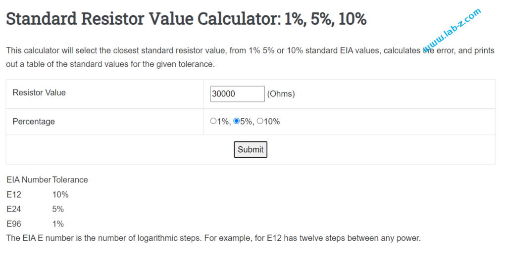
很多时候我们的设计需要使用电阻,但是你需要的电阻并不一定正好存在,比如,你的设计需要一个 1234Ω,很明显并不存在这个阻止的单一电阻。这时候就需要查询,这次推荐2个网站:
1.查询标准电阻,比如,需要30K 欧姆的电阻,可以在 下面这个网站查询到
https://www.daycounter.com/Calculators/Standard-Resistor-Value-Calculator.phtml
2.输入阻值自动给出建议
基本原理:通过 GetSystemPowerStatus 这个 API 获得当前系统的电池电量信息,以1秒为间隔进行查询,查询结果保存到文件中同时输出到屏幕上。收到按键后退出。
代码如下:
using System;
using System.Collections.Generic;
using System.Linq;
using System.Text;
using System.Threading.Tasks;
using System.Runtime.InteropServices;
using System.Threading;
using System.IO;
namespace GeetBatter
{

    class Program
    {
        [StructLayout(LayoutKind.Sequential)]
        public struct SYSTEM_POWER_STATUS
        {
            public byte ACLineStatus;
            public byte BatteryFlag;
            public byte BatteryLifePercent;
            public byte Reserved1;
            public int BatteryLifeTime;
            public int BatteryFullLifeTime;
        }

        [DllImport("kernel32.dll", CharSet = CharSet.Auto, ExactSpelling = true)]
        public static extern bool GetSystemPowerStatus([In, Out] ref SYSTEM_POWER_STATUS systemPowerStatus);

        static void Main(string[] args)
        {
            // The system power charger struct
            SYSTEM_POWER_STATUS status = new SYSTEM_POWER_STATUS();

            Boolean Running = true;
            DateTime currentTime;
            String Result;
            String Filename = DateTime.Now.ToString("HHmmss")+".txt";
            FileStream fs = new FileStream(Filename, FileMode.Append);
            StreamWriter wr = new StreamWriter(fs);

            while (Running)
            {
                Thread.Sleep(1000);
                while (Console.KeyAvailable)
                {
                    Console.ReadKey(true);
                    Running = false;
                }
                // Get Power status from Kernell
                GetSystemPowerStatus(ref status);

                currentTime = DateTime.Now;
                Result = currentTime.ToString("HH:mm:ss") + "," + status.BatteryLifePercent;
                Console.WriteLine(Result);
                wr.WriteLine(Result);
            }
            wr.Close();
            Console.WriteLine("Program would exit");
            Console.ReadLine();
        }
    }
}
对于风扇来说,只要供电就能工作。最开始的电脑使用的都是这种风扇。但是随着技术的发展,人们发现需要对这个风扇进行控制,因为风扇转的快噪音和功耗都会随之增加。于是,加上一根反馈线,让用户能够得知当前的转速。但是这样会遇到另外的两个问题:第一个问题是风扇电压变化,反馈线上的电压也会随之变化,范围大了读取这个反馈会很麻烦。第二个问题是:电压和风扇转速转速关系并不是线性的。比如,一个 12V 的风扇,12V时转速是 2000CPM,10V供电时转速时1000CPM,但是如果11V 供电时,转速很可能是 1100CPM。风扇的转速和风力噪音直接相关,用户想要得到一个大概的转速非常困难。最终 Intel 推出了一个方案:通过 PWM 来控制风扇转速,然后使用5V 信号作为当前转速反馈引脚。
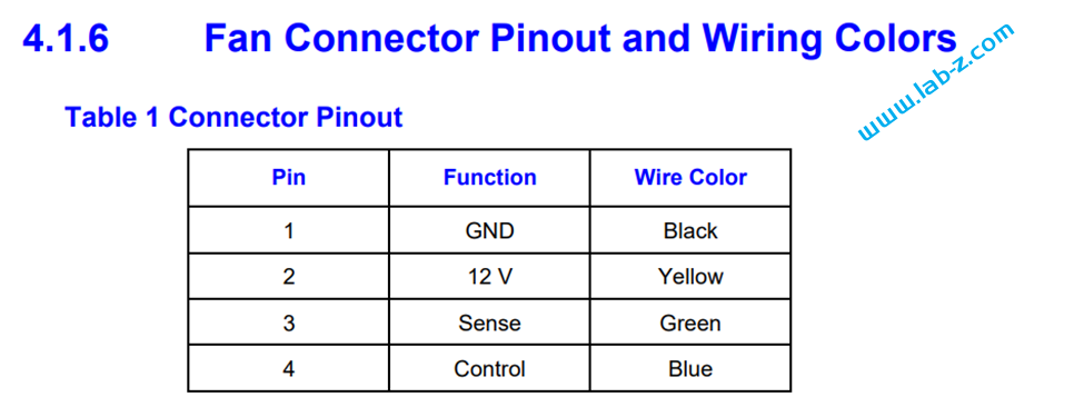
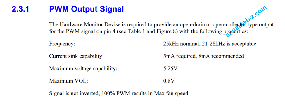
我们最常见到的CPU的风扇通常都是 4 Pin的。供电要求12V,控制的PWM 为 5V 25KHz,转速反馈引脚为 5V 输出。
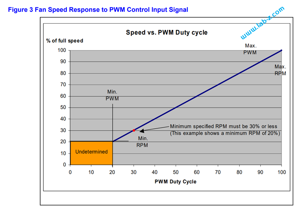
有些风扇是存在最低转速的,意思是哪怕有PWM 已经为0仍然能够旋转,有些不存在最低转速,PWM 比较低的时候就会停止转动。
了解了上述知识就可以得知我们为了实现控制 CPU 风扇,需要提供12V 电源,提供25Khz 的 PWM 信号,以及读取 5V 的转速输出。
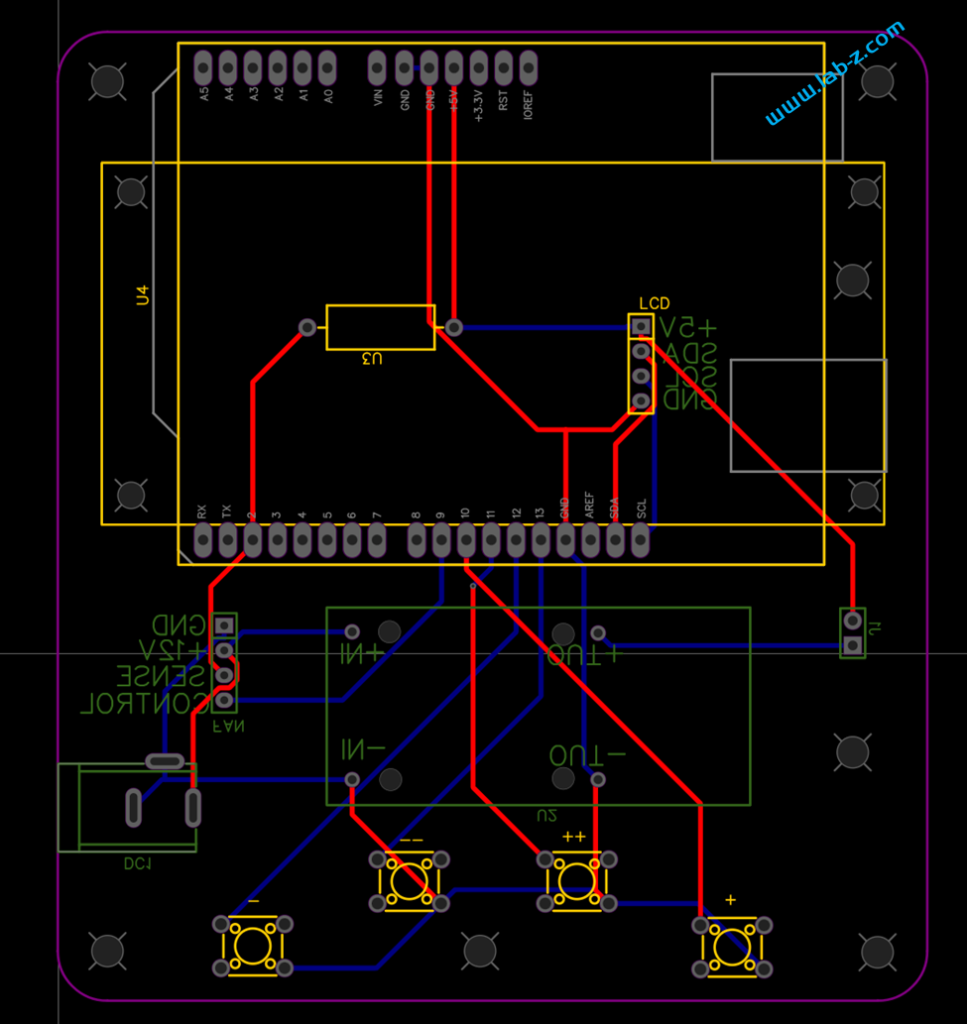
电路设计如下,我们使用 Arduino Uno作为主控。外部12V 供电进入(DC1)之后,经过一个DC-DC 降压模块(来自DFROBOT 的DFR0831,DC-DC降压模块7~24V转5V/4A),降压为5V提供给 Arduino 作为风扇控制,然后风扇的转速反馈信号经过U3上拉后进入Arduino 即可读取。最终转速和当前的PWM设定显示在一个 1602LCD上。
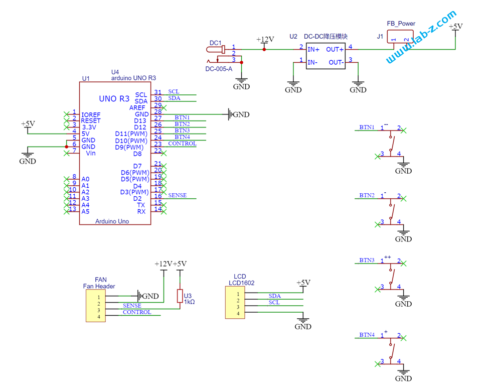
PCB 设计如下,可以看到板子上带有4个按钮用于控制 PWM ,分别是-1、-10、+1、+10这样用户可以快速的改变 PWM 设置。
代码设计如下:
#include <LiquidCrystal_I2C.h>
// 保存当前设定的 PWM 值
#include<EEPROM.h>

LiquidCrystal_I2C lcd(0x3F, 16, 2);

// PWM 发生器相关定义
const byte OC1A_PIN = 9; //PWM输出引脚为 D9
// 定义 PWM 频率
const word PWM_FREQ_HZ = 25000; //Adjust this value to adjust the frequency
const word TCNT1_TOP = 16000000 / (2 * PWM_FREQ_HZ);
const int BTN1 = 13;
const int BTN2 = 12;
const int BTN3 = 11;
const int BTN4 = 10;

// 计算转速相关定义
const int TOTAL = 10; // 计算10次输出一次,这是一个简单的滤波
int InterruptPin = 2;// 接收风扇中断 D2
volatile long int counter = 0;
volatile long int t[TOTAL];
byte p = 0;
byte SavedPWM = 0;
byte lastPWM = -1;
byte pwm;
long int Elsp=0;

void setup() {
  pinMode(BTN1, INPUT_PULLUP);
  pinMode(BTN2, INPUT_PULLUP);
  pinMode(BTN3, INPUT_PULLUP);
  pinMode(BTN4, INPUT_PULLUP);

  pinMode(OC1A_PIN, OUTPUT);

  // Clear Timer1 control and count registers
  TCCR1A = 0;
  TCCR1B = 0;
  TCNT1  = 0;

  // Set Timer1 configuration
  // COM1A(1:0) = 0b10   (Output A clear rising/set falling)
  // COM1B(1:0) = 0b00   (Output B normal operation)
  // WGM(13:10) = 0b1010 (Phase correct PWM)
  // ICNC1      = 0b0    (Input capture noise canceler disabled)
  // ICES1      = 0b0    (Input capture edge select disabled)
  // CS(12:10)  = 0b001  (Input clock select = clock/1)

  TCCR1A |= (1 << COM1A1) | (1 << WGM11);
  TCCR1B |= (1 << WGM13) | (1 << CS10);
  ICR1 = TCNT1_TOP;

  Serial.begin(115200);
  Serial.setTimeout(300);

  pinMode(InterruptPin, INPUT);
  attachInterrupt(0, speedX, FALLING );

  lcd.init();
  lcd.backlight();
  lcd.setCursor(0, 0);
  lcd.print("PWM Fan CNT");

  // PWM 存在地址0 上
  SavedPWM = EEPROM.read(0);

  if (SavedPWM>100) {
      SavedPWM=0;
    }
  // 将上一次保存的 PWM 设定进去
  setPwmDuty(SavedPWM);
  pwm = SavedPWM;
  lastPWM = pwm + 1;
}

void loop() {
  if (pwm != lastPWM) {
    Serial.println(pwm);
    setPwmDuty(pwm);
    lastPWM = pwm;
    Elsp=millis();
  }

  // 计算当前转速
  long int avg = 0;
  counter = 0;
  delay(1000);

  p = (p + 1) % TOTAL;
  t[p] = (long int)(counter * 60 / 2);

  for (byte i = 0; i < TOTAL; i++) {
    avg = avg + t[i];
  }

  // 输出转速
  Serial.print("Current speed: ");
  Serial.println(avg / TOTAL);

  lcd.setCursor(0, 1);
  lcd.print("Fan Speed:");
  lcd.print(avg / TOTAL);
  lcd.print("      ");

  counter = 0;
  pinMode(BTN1, INPUT_PULLUP);
  if (digitalRead(BTN1) == LOW) {
    delay(5);
    if ((digitalRead(BTN1) == LOW) && (pwm > 9)) {
      pwm = pwm - 10;
    }
  }
  if (digitalRead(BTN2) == LOW) {
    delay(5);
    if ((digitalRead(BTN2) == LOW) && (pwm > 0)) {
      pwm = pwm - 1;
    }
  }
  if (digitalRead(BTN3) == LOW) {
    delay(5);
    if ((digitalRead(BTN3) == LOW) && (pwm <=100-10)) {
      pwm = pwm + 10;
    }
  }
  if (digitalRead(BTN4) == LOW) {
    delay(5);
    if ((digitalRead(BTN4) == LOW) && (pwm <100)) {
      pwm = pwm + 1;
    }
  }

  // 每隔5秒检查 pwm 是否已经改变,如果改变则保存
  if ((SavedPWM!=pwm)&&(millis()-Elsp>5000)) {
      Serial.println("Save current pwm");
      Elsp=millis();
      SavedPWM=pwm;
      EEPROM.write(0,pwm);
    }
}

void setPwmDuty(byte duty) {
  Serial.print("Set pwm "); Serial.println(duty);
  lcd.setCursor(0, 0);
  lcd.print("Current pwm:");
  lcd.print(duty);
  lcd.print("  ");
  OCR1A = (word) (duty * TCNT1_TOP)/ 100;
}


void speedX()//中断函数
{
  counter++;
}
4 Pin fan 的 spec:
本文提到的电路图和PCB:
这里分享一个VS2019 Visual C++ 离线安装包,下载之后可以直接安装无需联网。
提取码: labz
之前基于 FireBeetle ESP32 和全向MEMS麦克风模块(SEN0487)制作过一个在OLED 屏幕上显示当前环境声音频谱的装置【参考1】。这次制作的是能够输出 VGA 信号的频谱装置,这样,用户能够在显示器或者电视机上看到实时频谱输出。
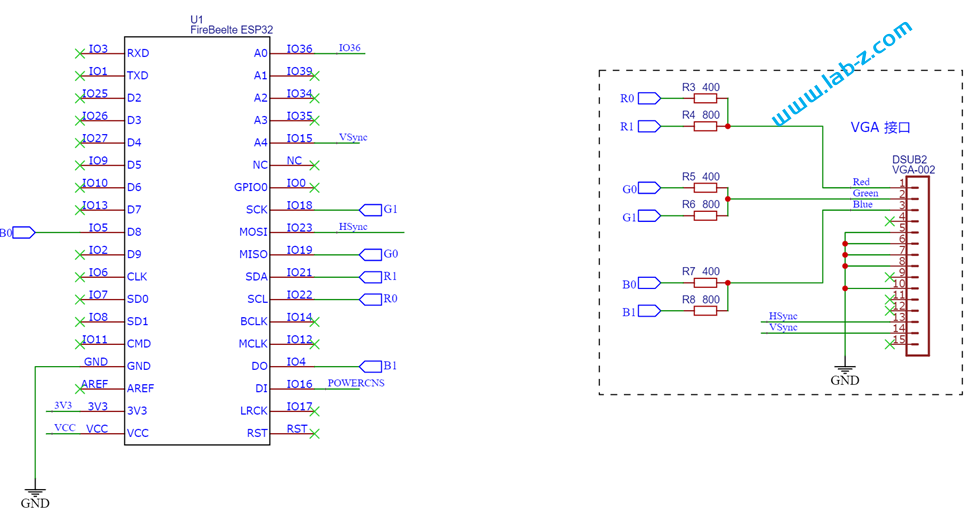
具体的VGA 显示原理,可以在之前的介绍中看到【参考2】,这次的设计硬件部分与之类似。电路图如下:
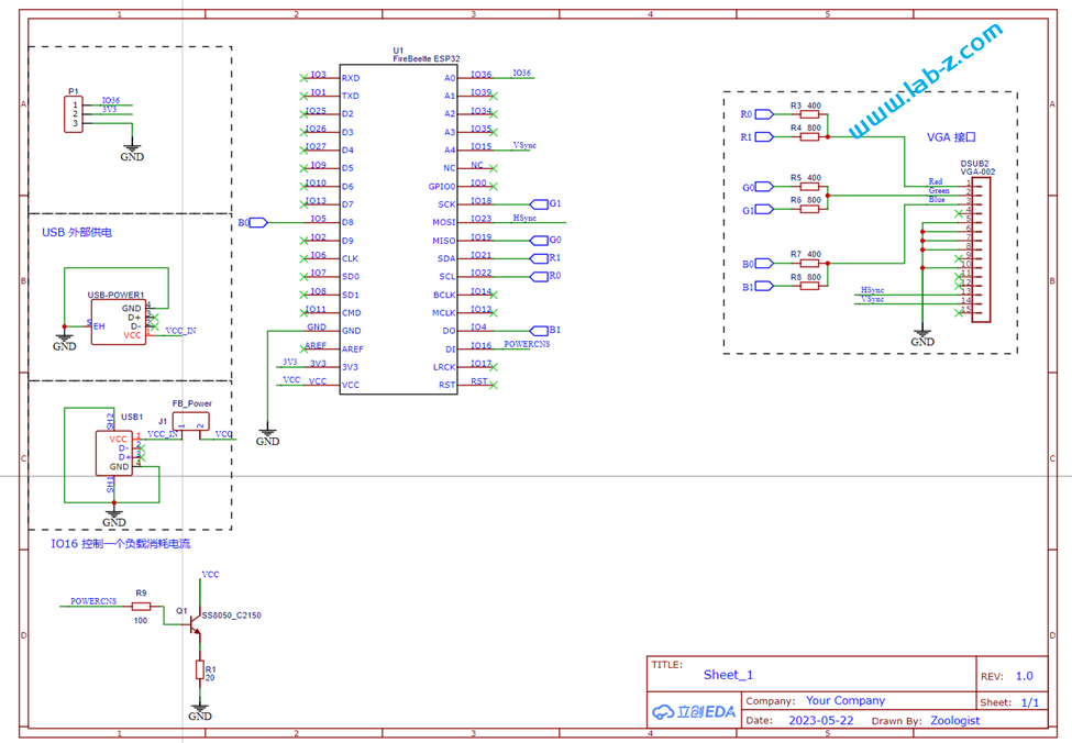
其中主控和VGA 部分如下:VGA本质上还是模拟信号,这里使用电阻能够输出不同电平的模拟信号,三根GPIO能够实现2^3=16种组合,因此也意味着能够实现16种颜色.
下面是用于连接全向MEMS麦克风模块的接口:
板子上带有一个 USB 公头用于取电,另外还有一个 USB母头,如果你的显示设备没有 VGA接口只有HDMI接口,那么需要一个VGA转HDMI线,而这种线通常使用USB公头取电,这种情况可以直接将它连接到这个 USB母头取电。
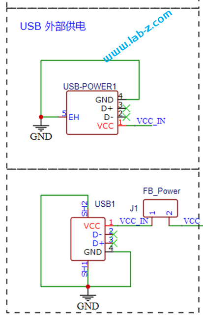
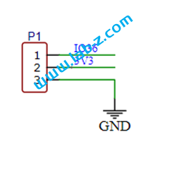
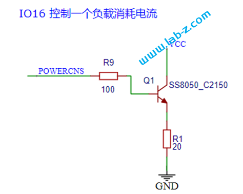
同样的,为了便于从充电宝取电,还设计了一个负载消耗电路。
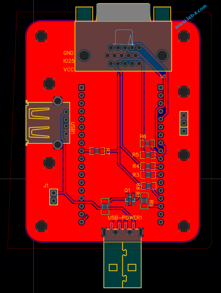
PCB设计如下:
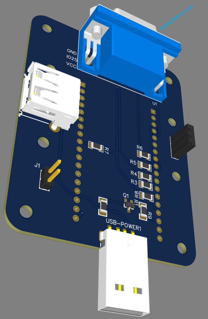
3D预览如下:
焊接后的实物如下:
接下来就可以进行软件的设计了,。基本原理是:首先通过ADC进行采样,然后将采样结果进行 FFT ,最终得到的是采样期间每个频率的能量。我们将这个数值显示在 VGA上就得到了期望的结果:
#include <arduinoFFT.h>
#include "fabgl.h"

// VGA 显示
fabgl::VGA16Controller DisplayController;
Canvas cv(&DisplayController);

//ZivDebug #define SAMPLES         1024          // Must be a power of 2
#define SAMPLES         256          // Must be a power of 2
#define SAMPLING_FREQ   40000         // Hz, must be 40000 or less due to ADC conversion time. Determines maximum frequency that can be analysed by the FFT Fmax=sampleF/2.
#define AMPLITUDE       1000          // Depending on your audio source level, you may need to alter this value. Can be used as a 'sensitivity' control.
#define AUDIO_IN_PIN    A0            // Signal in on this pin

#define NOISE           500           // Used as a crude noise filter, values below this are ignored
const uint8_t kMatrixWidth = 16;      // Matrix width
const uint8_t kMatrixHeight = 16;     // Matrix height

#define NUM_BANDS       16            // To change this, you will need to change the bunch of if statements describing the mapping from bins to bands

#define BAR_WIDTH      (kMatrixWidth  / (NUM_BANDS - 1))  // If width >= 8 light 1 LED width per bar, >= 16 light 2 LEDs width bar etc
#define TOP            (kMatrixHeight - 0)                // Don't allow the bars to go offscreen

// Sampling and FFT stuff
unsigned int sampling_period_us;
byte peak[] = {0, 0, 0, 0, 0, 0, 0, 0, 0, 0, 0, 0, 0, 0, 0, 0}; // The length of these arrays must be >= NUM_BANDS
int oldBarHeights[] = {0, 0, 0, 0, 0, 0, 0, 0, 0, 0, 0, 0, 0, 0, 0, 0};
int bandValues[] = {0, 0, 0, 0, 0, 0, 0, 0, 0, 0, 0, 0, 0, 0, 0, 0};
double vReal[SAMPLES];
double vImag[SAMPLES];
unsigned long newTime;

arduinoFFT FFT = arduinoFFT(vReal, vImag, SAMPLES, SAMPLING_FREQ);

unsigned long int Elsp1;
int h[16];
int Height,Width;

void setup() {
  Serial.begin(115200);
  sampling_period_us = round(1000000 * (1.0 / SAMPLING_FREQ));
  DisplayController.begin();
  // 设定分辨率
  DisplayController.setResolution(VGA_640x400_60Hz);
  Height=cv.getHeight();
  Width=cv.getWidth();

  cv.setBrushColor(Color::Red    );

  // get a font for about 40x14 text screen
  cv.selectFont(&fabgl::FONT_8x8);

  cv.setGlyphOptions(GlyphOptions().FillBackground(true));

}

void loop() {
  static int64_t stime  = esp_timer_get_time();
  static int FPS        = 0;
  static int FPSCounter = 0;


  // Reset bandValues[]
  for (int i = 0; i < NUM_BANDS; i++) {
    bandValues[i] = 0;
  }

  // Sample the audio pin
  for (int i = 0; i < SAMPLES; i++) {
    newTime = micros();
    vReal[i] = analogRead(AUDIO_IN_PIN); // A conversion takes about 9.7uS on an ESP32
    vImag[i] = 0;
    while ((micros() - newTime) < sampling_period_us) {
      /* chill */
    }
  }

  // Compute FFT
  FFT.DCRemoval();
  FFT.Windowing(FFT_WIN_TYP_HAMMING, FFT_FORWARD);
  FFT.Compute(FFT_FORWARD);
  FFT.ComplexToMagnitude();

  // Analyse FFT results
  for (int i = 2; i < (SAMPLES / 2); i++) {    // Don't use sample 0 and only first SAMPLES/2 are usable. Each array element represents a frequency bin and its value the amplitude.
    if (vReal[i] > NOISE) {                    // Add a crude noise filter

      //16 bands, 12kHz top band
      if (i <= 2 )           bandValues[0]  += (int)vReal[i];
      if (i > 2   && i <= 3  ) bandValues[1]  += (int)vReal[i];
      if (i > 3   && i <= 5  ) bandValues[2]  += (int)vReal[i];
      if (i > 5   && i <= 7  ) bandValues[3]  += (int)vReal[i];
      if (i > 7   && i <= 9  ) bandValues[4]  += (int)vReal[i];
      if (i > 9   && i <= 13 ) bandValues[5]  += (int)vReal[i];
      if (i > 13  && i <= 18 ) bandValues[6]  += (int)vReal[i];
      if (i > 18  && i <= 25 ) bandValues[7]  += (int)vReal[i];
      if (i > 25  && i <= 36 ) bandValues[8]  += (int)vReal[i];
      if (i > 36  && i <= 50 ) bandValues[9]  += (int)vReal[i];
      if (i > 50  && i <= 69 ) bandValues[10] += (int)vReal[i];
      if (i > 69  && i <= 97 ) bandValues[11] += (int)vReal[i];
      if (i > 97  && i <= 135) bandValues[12] += (int)vReal[i];
      if (i > 135 && i <= 189) bandValues[13] += (int)vReal[i];
      if (i > 189 && i <= 264) bandValues[14] += (int)vReal[i];
      if (i > 264          ) bandValues[15] += (int)vReal[i];
    }
  }

  // Process the FFT data into bar heights
  for (byte band = 0; band < NUM_BANDS; band++) {

    // Scale the bars for the display
    int barHeight = bandValues[band] / AMPLITUDE;
    if (barHeight > TOP) barHeight = TOP;

    // Small amount of averaging between frames
    barHeight = ((oldBarHeights[band] * 1) + barHeight) / 2;

    // Move peak up
    if (barHeight > peak[band]) {
      peak[band] = min(TOP, barHeight);
    }
    h[band] = barHeight;

    // Save oldBarHeights for averaging later
    oldBarHeights[band] = barHeight;

  }

  if (millis() - Elsp1 > 10) {
    for (byte band = 0; band < NUM_BANDS; band++)
      if (peak[band] > 0) peak[band] -= 1;


    cv.setBrushColor(Color::Black    );
    cv.clear();
    cv.setBrushColor(Color::Red    );
    for (int i = 0; i < 16; i++) {
      if (h[i] != 0) {
        //cv.fillRectangle(cv.getWidth()*i / 16, 0, cv.getWidth() * (i + 1) / 16, cv.getHeight() *h[i] / 16);
        cv.fillRectangle(Width*i / 16, Height -1 , Width * (i + 1) / 16-1, (Height-1) *(16-h[i]) / 16);

      }
      Serial.print(h[i], HEX);
      Serial.print("");
    }
    Serial.println("");

    Elsp1 = millis();
  }

      if (esp_timer_get_time() - stime > 1000000) {
    // calculate FPS
    FPS = FPSCounter;
    stime = esp_timer_get_time();
    FPSCounter = 0;
  }
  ++FPSCounter;

  // display test state and FPS
  cv.setPenColor(Color::Blue);
  cv.setBrushColor(Color::Yellow);
  cv.drawTextFmt(80, 5, "%d FPS ",  FPS);
}
参考:
本文提到的电路图下载:
本文提到的完整代码:
Visual Studio 的 C 支持 #pragma message() 宏可以用来输出一些信息。于是编写一个代码进行测试:
#include  <Uefi.h>
#include  <Library/UefiLib.h>
#include  <Library/ShellCEntryLib.h>

/***
  Print a welcoming message.

  Establishes the main structure of the application.

  @retval  0         The application exited normally.
  @retval  Other     An error occurred.
***/
INTN
EFIAPI
ShellAppMain (
  IN UINTN Argc,
  IN CHAR16 **Argv
  )
{
  #pragma message (__FILE__)
    return(0);
}
唯一的问题是:我在 EDK2 中编译的时候,无法看到输出的结果。经过研究,编译C代码是通过下面这个指令:
"C:\Program Files (x86)\Microsoft Visual Studio\2019\Professional\VC\Tools\MSVC\14.29.30133\bin\Hostx86\x64\cl.exe" /Foc:\buildbs\edk2-edk2-stable202205\Build\AppPkg\DEBUG_VS2019\X64\AppPkg\Applications\HelloMacro\HelloMacro\OUTPUT\.\ /showIncludes /nologo /c /WX /GS- /W4 /Gs32768 /D UNICODE /O1b2s /GL /Gy /FIAutoGen.h /EHs-c- /GR- /GF /Z7 /Gw /X /Zc:wchar_t /D UEFI_C_SOURCE /Wv:11 /Ic:\buildbs\edk2-edk2-stable202205\AppPkg\Applications\HelloMacro /Ic:\buildbs\edk2-edk2-stable202205\Build\AppPkg\DEBUG_VS2019\X64\AppPkg\Applications\HelloMacro\HelloMacro\DEBUG /Ic:\buildbs\edk2-edk2-stable202205\MdePkg /Ic:\buildbs\edk2-edk2-stable202205\MdePkg\Include /Ic:\buildbs\edk2-edk2-stable202205\MdePkg\Test\UnitTest\Include /Ic:\buildbs\edk2-edk2-stable202205\MdePkg\Include\X64 /Ic:\buildbs\edk2-edk2-stable202205\ShellPkg /Ic:\buildbs\edk2-edk2-stable202205\ShellPkg\Include @c:\buildbs\edk2-edk2-stable202205\Build\AppPkg\DEBUG_VS2019\X64\AppPkg\Applications\HelloMacro\HelloMacro\OUTPUT\cc_resp_1.txt
于是尝试去掉其中的/nologo 指令,运行结果如下:
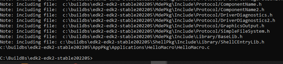
再同时去掉 /showIncludes 运行结果:
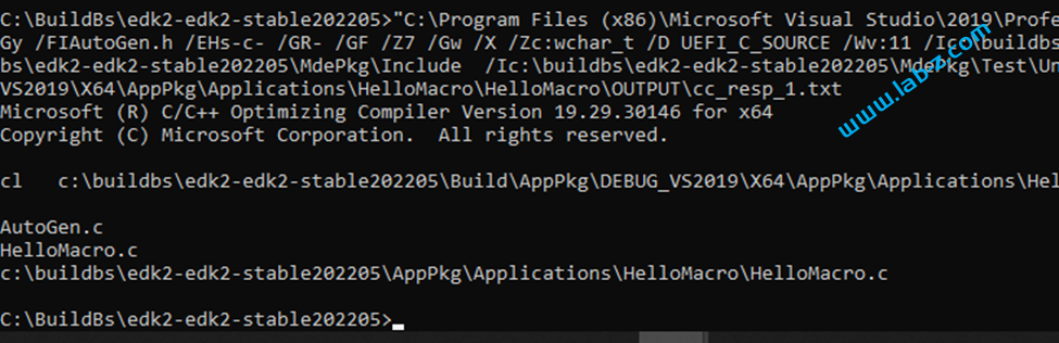
可以看到,其中出现了当前的文件名信息。
总结:在使用VC 编写代码的时候,如果需要输出一些编译期的数据,可以考虑使用 #pragma message() 来实现。