text
help = STRING_TOKEN(STR_NULL_STRING),
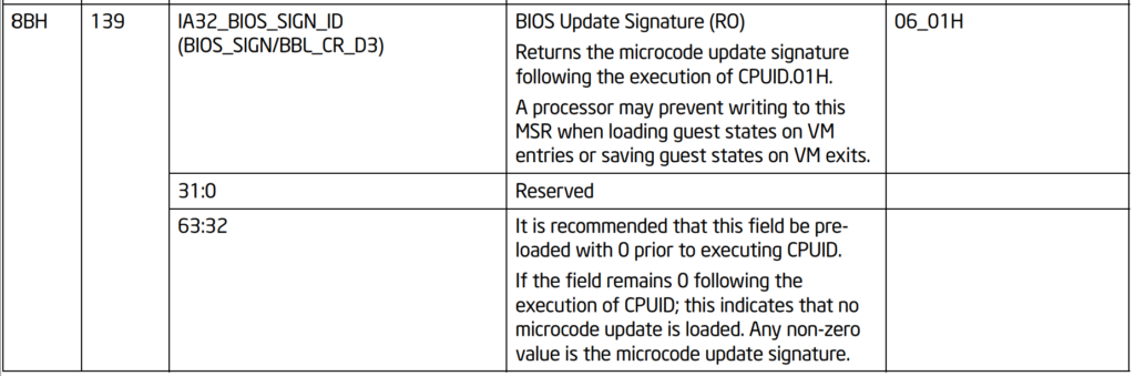
text = STRING_TOKEN(STR_PROCESSOR_MICROCODE_STRING),
text = STRING_TOKEN(STR_PROCESSOR_MICROCODE_VALUE),
flags = 0,
key = 0;
/**
  Returns a 64-bit Machine Specific Register(MSR).

  Reads and returns the 64-bit MSR specified by Index. No parameter checking is
  performed on Index, and some Index values may cause CPU exceptions. The
  caller must either guarantee that Index is valid, or the caller must set up
  exception handlers to catch the exceptions. This function is only available
  on IA-32 and x64.

  @param  Index The 32-bit MSR index to read.

  @return The value of the MSR identified by Index.

**/
UINT64
EFIAPI
AsmReadMsr64 (
  IN      UINT32                    Index
  );
typedef
EFI_STATUS
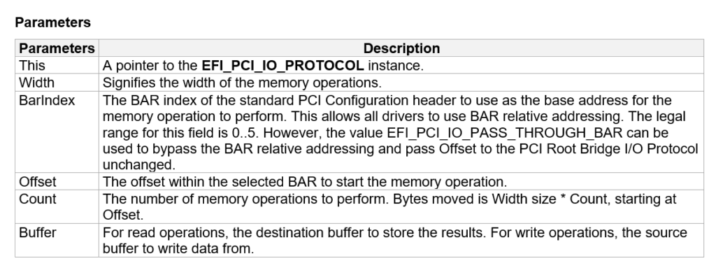
(EFIAPI *EFI_PCI_IO_PROTOCOL_MEM) (
IN EFI_PCI_IO_PROTOCOL *This,
IN EFI_PCI_IO_PROTOCOL_WIDTH Width,
IN UINT8 BarIndex,
IN UINT64 Offset,
IN UINTN Count,
IN OUT VOID *Buffer
);
#include <Library/BaseLib.h>
#include <Uefi.h>
#include <Library/UefiLib.h>
#include <Library/PrintLib.h>
#include <Library/ShellCEntryLib.h>
#include <Protocol/PciIo.h>
#include <IndustryStandard/Pci22.h>
#include <Library/MemoryAllocationLib.h>
extern EFI_BOOT_SERVICES *gBS;
extern EFI_HANDLE gImageHandle;
/***
Demonstrates basic workings of the main() function by displaying a
welcoming message.
Note that the UEFI command line is composed of 16-bit UCS2 wide characters.
The easiest way to access the command line parameters is to cast Argv as:
wchar_t **wArgv = (wchar_t **)Argv;
@param[in] Argc Number of argument tokens pointed to by Argv.
@param[in] Argv Array of Argc pointers to command line tokens.
@retval 0 The application exited normally.
@retval Other An error occurred.
***/
int
main (
IN int Argc,
IN char **Argv
)
{
EFI_STATUS Status;
EFI_PCI_IO_PROTOCOL *PciIo;
UINTN Seg,Bus,Dev,Fun;
UINT32 Index;
UINT32 tmp;
Status = gBS->LocateProtocol(
&gEfiPciIoProtocolGuid,
NULL,
(VOID **) &PciIo);
if (EFI_ERROR(Status)) {
Print(L"Couldn't find PCIIO Protocol\n");
return EFI_SUCCESS;
}
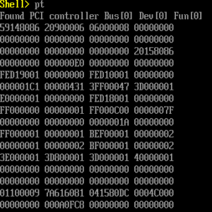
PciIo->GetLocation(PciIo,&Seg,&Bus,&Dev,&Fun);
Print(L"Found PCI controller Bus[%d] Dev[%d] Fun[%d]\n",
Bus,Dev,Fun);
for (Index = 0; Index < 256/4; Index++) {
Status = PciIo->Pci.Read (
PciIo,
EfiPciIoWidthUint32,
Index*4,
1,
&tmp);
Print(L"%08X ",tmp);
if ((Index+1)%4==0) {Print(L"\n");}
}
return 0;
}
/** @file
A simple, basic, EDK II native, "hello" application to verify that
we can build applications without LibC.
Copyright (c) 2010 - 2011, Intel Corporation. All rights reserved.<BR>
This program and the accompanying materials
are licensed and made available under the terms and conditions of the BSD License
which accompanies this distribution. The full text of the license may be found at
http://opensource.org/licenses/bsd-license.
THE PROGRAM IS DISTRIBUTED UNDER THE BSD LICENSE ON AN "AS IS" BASIS,
WITHOUT WARRANTIES OR REPRESENTATIONS OF ANY KIND, EITHER EXPRESS OR IMPLIED.
**/
#include <Uefi.h>
#include <Library/UefiLib.h>
#include <Library/ShellCEntryLib.h>
#include <Library/UefiBootServicesTableLib.h> //global gST gBS gImageHandle
#include <Library/ShellLib.h>
extern EFI_RUNTIME_SERVICES *gRT;
EFI_TIME ET;
/***
Print a welcoming message.
Establishes the main structure of the application.
@retval 0 The application exited normally.
@retval Other An error occurred.
***/
INTN
EFIAPI
ShellAppMain (
IN UINTN Argc,
IN CHAR16 **Argv
)
{
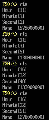
gRT->GetTime(&ET,NULL);
Print(L"Hour [%d]\n",ET.Hour);
Print(L"Minute[%d]\n",ET.Minute);
Print(L"Second[%d]\n",ET.Second);
Print(L"Nano [%d]\n",ET.Nanosecond);
return(0);
}
EFI_STATUS
EFIAPI
InitializeRealTimeClock (
  IN EFI_HANDLE                            ImageHandle,
  IN EFI_SYSTEM_TABLE                      *SystemTable
  )
  SystemTable->RuntimeServices->GetTime       = WinNtGetTime;
  SystemTable->RuntimeServices->SetTime       = WinNtSetTime;
具体实现
EFI_STATUS
EFIAPI
WinNtGetTime (
  OUT EFI_TIME                                 *Time,
  OUT EFI_TIME_CAPABILITIES                    *Capabilities OPTIONAL
  )
/*++

Routine Description:
  Service routine for RealTimeClockInstance->GetTime

Arguments:

  Time          - A pointer to storage that will receive a snapshot of the current time.

  Capabilities  - A pointer to storage that will receive the capabilities of the real time clock
                  in the platform. This includes the real time clock's resolution and accuracy.
                  All reported device capabilities are rounded up.  This is an OPTIONAL argument.

Returns:

  EFI_SUCEESS   - The underlying GetSystemTime call occurred and returned
                  Note that in the NT32 emulation, the GetSystemTime call has no return value
                  thus you will always receive a EFI_SUCCESS on this.

--*/
// TODO:    EFI_INVALID_PARAMETER - add return value to function comment
{
  SYSTEMTIME            SystemTime;
  TIME_ZONE_INFORMATION TimeZone;

  //
  // Check parameter for null pointer
  //
  if (Time == NULL) {
    return EFI_INVALID_PARAMETER;

  }

  gWinNt->GetLocalTime (&SystemTime);
  gWinNt->GetTimeZoneInformation (&TimeZone);

  Time->Year        = (UINT16) SystemTime.wYear;
  Time->Month       = (UINT8) SystemTime.wMonth;
  Time->Day         = (UINT8) SystemTime.wDay;
  Time->Hour        = (UINT8) SystemTime.wHour;
  Time->Minute      = (UINT8) SystemTime.wMinute;
  Time->Second      = (UINT8) SystemTime.wSecond;
  Time->Nanosecond  = (UINT32) (SystemTime.wMilliseconds * 1000000);
  Time->TimeZone    = (INT16) TimeZone.Bias;

  if (Capabilities != NULL) {
    Capabilities->Resolution  = 1;
    Capabilities->Accuracy    = 50000000;
    Capabilities->SetsToZero  = FALSE;
  }

  Time->Daylight = 0;
  if (TimeZone.StandardDate.wMonth) {
    Time->Daylight = (UINT8) TimeZone.StandardDate.wMonth;
  }

  return EFI_SUCCESS;
}
/**
  Converts time read from RTC to EFI_TIME format defined by UEFI spec.

  This function converts raw time data read from RTC to the EFI_TIME format
  defined by UEFI spec.
  If data mode of RTC is BCD, then converts it to decimal,
  If RTC is in 12-hour format, then converts it to 24-hour format.

  @param   Time       On input, the time data read from RTC to convert
                      On output, the time converted to UEFI format
  @param   RegisterB  Value of Register B of RTC, indicating data mode
                      and hour format.

  @retval  EFI_INVALID_PARAMETER  Parameters passed in are invalid.
  @retval  EFI_SUCCESS            Convert RTC time to EFI time successfully.

**/
EFI_STATUS
ConvertRtcTimeToEfiTime (
  IN OUT EFI_TIME        *Time,
  IN     RTC_REGISTER_B  RegisterB
  )
{
  BOOLEAN IsPM;
  UINT8   Century;

  if ((Time->Hour & 0x80) != 0) {
    IsPM = TRUE;
  } else {
    IsPM = FALSE;
  }

  Time->Hour = (UINT8) (Time->Hour & 0x7f);

  if (RegisterB.Bits.Dm == 0) {
    Time->Year    = CheckAndConvertBcd8ToDecimal8 ((UINT8) Time->Year);
    Time->Month   = CheckAndConvertBcd8ToDecimal8 (Time->Month);
    Time->Day     = CheckAndConvertBcd8ToDecimal8 (Time->Day);
    Time->Hour    = CheckAndConvertBcd8ToDecimal8 (Time->Hour);
    Time->Minute  = CheckAndConvertBcd8ToDecimal8 (Time->Minute);
    Time->Second  = CheckAndConvertBcd8ToDecimal8 (Time->Second);
  }

  if (Time->Year == 0xff || Time->Month == 0xff || Time->Day == 0xff ||
      Time->Hour == 0xff || Time->Minute == 0xff || Time->Second == 0xff) {
    return EFI_INVALID_PARAMETER;
  }

  //
  // For minimal/maximum year range [1970, 2069],
  //   Century is 19 if RTC year >= 70,
  //   Century is 20 otherwise.
  //
  Century = (UINT8) (PcdGet16 (PcdMinimalValidYear) / 100);
  if (Time->Year < PcdGet16 (PcdMinimalValidYear) % 100) {
    Century++;
  }
  Time->Year = (UINT16) (Century * 100 + Time->Year);

  //
  // If time is in 12 hour format, convert it to 24 hour format
  //
  if (RegisterB.Bits.Mil == 0) {
    if (IsPM && Time->Hour < 12) {
      Time->Hour = (UINT8) (Time->Hour + 12);
    }

    if (!IsPM && Time->Hour == 12) {
      Time->Hour = 0;
    }
  }

  Time->Nanosecond  = 0;

  return EFI_SUCCESS;
}
/**
  Saves the current CPU context that can be restored with a call to LongJump()
  and returns 0.

  Saves the current CPU context in the buffer specified by JumpBuffer and
  returns 0. The initial call to SetJump() must always return 0. Subsequent
  calls to LongJump() cause a non-zero value to be returned by SetJump().

  If JumpBuffer is NULL, then ASSERT().
  For Itanium processors, if JumpBuffer is not aligned on a 16-byte boundary, then ASSERT().

  NOTE: The structure BASE_LIBRARY_JUMP_BUFFER is CPU architecture specific.
  The same structure must never be used for more than one CPU architecture context.
  For example, a BASE_LIBRARY_JUMP_BUFFER allocated by an IA-32 module must never be used from an x64 module.
  SetJump()/LongJump() is not currently supported for the EBC processor type.

  @param  JumpBuffer  A pointer to CPU context buffer.

  @retval 0 Indicates a return from SetJump().

**/
RETURNS_TWICE
UINTN
EFIAPI
SetJump (
  OUT     BASE_LIBRARY_JUMP_BUFFER  *JumpBuffer
  );
从介绍上来看,SetJump能保存调用处的全部寄存器,然后返回到调用的位置。
/**
  Restores the CPU context that was saved with SetJump().

  Restores the CPU context from the buffer specified by JumpBuffer. This
  function never returns to the caller. Instead is resumes execution based on
  the state of JumpBuffer.

  If JumpBuffer is NULL, then ASSERT().
  For Itanium processors, if JumpBuffer is not aligned on a 16-byte boundary, then ASSERT().
  If Value is 0, then ASSERT().

  @param  JumpBuffer  A pointer to CPU context buffer.
  @param  Value       The value to return when the SetJump() context is
                      restored and must be non-zero.

**/
VOID
EFIAPI
LongJump (
  IN      BASE_LIBRARY_JUMP_BUFFER  *JumpBuffer,
  IN      UINTN                     Value
  );