/**
  On Ready To Boot Services Event notification handler.

  Notify SMM variable driver about the event.

  @param[in]  Event     Event whose notification function is being invoked
  @param[in]  Context   Pointer to the notification function's context

**/
VOID
EFIAPI
OnMyReadyToBoot (
  IN      EFI_EVENT                         Event,
  IN      VOID                              *Context
  )
{
  DEBUG ((EFI_D_INFO, "Invoke OnMyReadyToBoot\n"));

  for (UINTN i=0;i<5;i++) {
	gST->ConOut->OutputString(gST->ConOut,L"\r\n delay from www.lab-z.com\r\n");
	gBS->Stall(1000000UL);
  }

  gBS->CloseEvent (Event);
}
       // null terminate it.  Safe even if nChars==0 because it is 1 TCHAR bigger
       *(lpch+nChars)= (TCHAR) 0;

       // Set 'fLog' if first characters in file are ".LOG"
       fLog= *lpch++ == TEXT('.') && *lpch++ == TEXT('L') &&
             *lpch++ == TEXT('O') && *lpch == TEXT('G');
之后,同样文件还有根据标志位进行动作的代码:
    /* If file starts with ".LOG" go to end and stamp date time */
    if (fLog)
    {
       SendMessage( hwndEdit, EM_SETSEL, (WPARAM)nChars, (LPARAM)nChars);
       SendMessage( hwndEdit, EM_SCROLLCARET, 0, 0);
       InsertDateTime(TRUE);
}
为了验证猜想,我对上述代码进行修改,判断条件之后除了增加时间再增加一段我自定义的字符串:
    /* If file starts with ".LOG" go to end and stamp date time */
    if (fLog)
    {
       SendMessage( hwndEdit, EM_SETSEL, (WPARAM)nChars, (LPARAM)nChars);
       SendMessage( hwndEdit, EM_SCROLLCARET, 0, 0);
       InsertDateTime(TRUE);
	   //LABZ_Debug_Start
	   TCHAR szMsg[] = TEXT("www.lab-z.com");
	   SendMessage(hwndEdit, EM_REPLACESEL, TRUE, (LPARAM)szMsg);
	   //LABZ_Debug_End
}
#include <Wire.h>
#include <Adafruit_Sensor.h>
#include <Mahony_BMX160.h>
#include <Madgwick_BMX160.h>
#include <DPEng_BMX160.h>
// Create sensor instance.
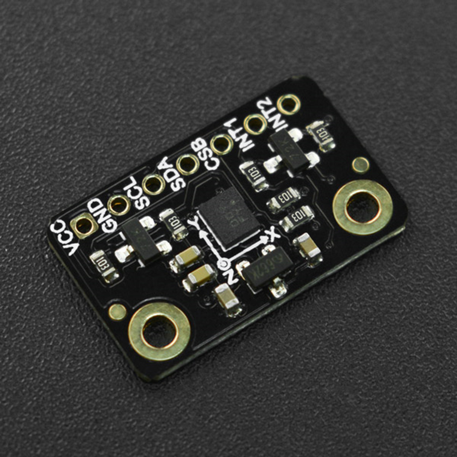
DPEng_BMX160 dpEng = DPEng_BMX160(0x160A, 0x160B, 0x160C);
// Mag calibration values are calculated via ahrs_calibration example sketch results.
// These values must be determined for each baord/environment.
// See the image in this sketch folder for the values used
// below.
// Offsets applied to raw x/y/z mag values
float mag_offsets[3] = { 9.83F, 4.42F, -6.97F };
// Soft iron error compensation matrix
float mag_softiron_matrix[3][3] = { { 0.586, 0.006, 0.001 },
{ 0.006, 0.601, -0.002 },
{ 0.001, -0.002, 2.835 } };
float mag_field_strength = 56.33F;
// Offsets applied to compensate for gyro zero-drift error for x/y/z
float gyro_zero_offsets[3] = { 0.0F, 0.0F, 0.0F };
// Mahony is lighter weight as a filter and should be used
// on slower systems
Mahony_BMX160 filter;
//Madgwick_BMX160 filter;
void setup()
{
Serial.begin(115200);
// Wait for the Serial Monitor to open (comment out to run without Serial Monitor)
// while(!Serial);
Serial.println(F("DPEng AHRS Fusion Example")); Serial.println("");
// Initialize the sensors.
if(!dpEng.begin(BMX160_ACCELRANGE_4G, GYRO_RANGE_250DPS))
{
/* There was a problem detecting the BMX160 ... check your connections */
Serial.println("Ooops, no BMX160 detected ... Check your wiring!");
while(1);
}
filter.begin();
}
void loop(void)
{
sensors_event_t accel_event;
sensors_event_t gyro_event;
sensors_event_t mag_event;
// Get new data samples
dpEng.getEvent(&accel_event, &gyro_event, &mag_event);
// Apply mag offset compensation (base values in uTesla)
float x = mag_event.magnetic.x - mag_offsets[0];
float y = mag_event.magnetic.y - mag_offsets[1];
float z = mag_event.magnetic.z - mag_offsets[2];
// Apply mag soft iron error compensation
float mx = x * mag_softiron_matrix[0][0] + y * mag_softiron_matrix[0][1] + z * mag_softiron_matrix[0][2];
float my = x * mag_softiron_matrix[1][0] + y * mag_softiron_matrix[1][1] + z * mag_softiron_matrix[1][2];
float mz = x * mag_softiron_matrix[2][0] + y * mag_softiron_matrix[2][1] + z * mag_softiron_matrix[2][2];
// Apply gyro zero-rate error compensation
float gx = gyro_event.gyro.x + gyro_zero_offsets[0];
float gy = gyro_event.gyro.y + gyro_zero_offsets[1];
float gz = gyro_event.gyro.z + gyro_zero_offsets[2];
// Update the filter
filter.update(gx, gy, gz,
accel_event.acceleration.x, accel_event.acceleration.y, accel_event.acceleration.z,
mx, my, mz,
mag_event.timestamp);
// Print the orientation filter output
// Note: To avoid gimbal lock you should read quaternions not Euler
// angles, but Euler angles are used here since they are easier to
// understand looking at the raw values. See the ble fusion sketch for
// and example of working with quaternion data.
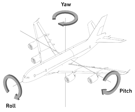
float roll = filter.getRoll();
float pitch = filter.getPitch();
float heading = filter.getYaw();
//Serial.print(millis());
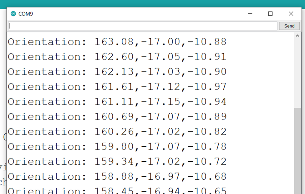
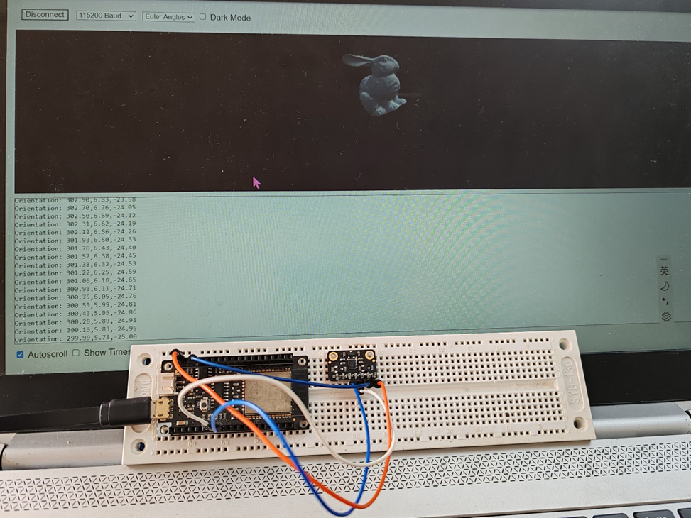
Serial.print("Orientation: ");
Serial.print(heading);
Serial.print(",");
Serial.print(pitch);
Serial.print(",");
Serial.println(roll);
delay(100);
}
在串口管理器中看到输出表明工作正常之后就可以进行下一步。
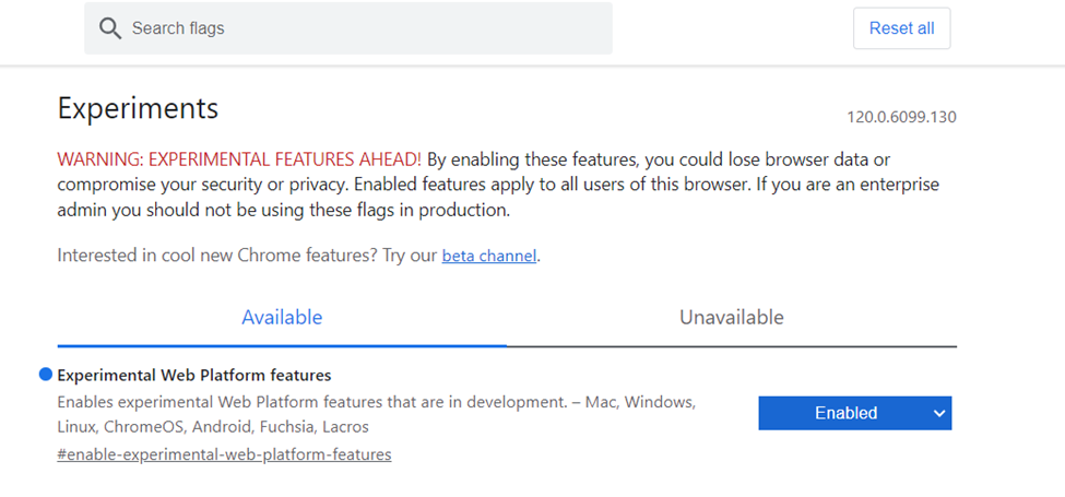
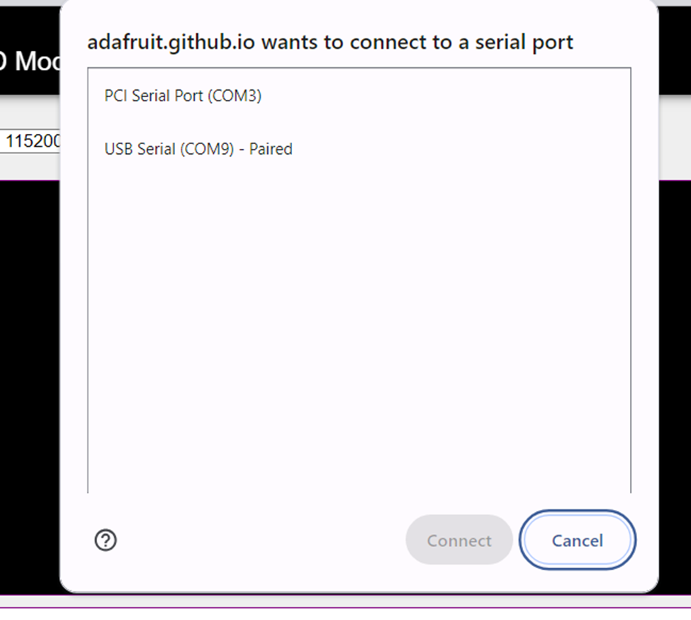
我们需要网页读取串口数据,在 Chrome 上地址栏输入 chrome://flags,打开 Experimental Web Platform features: