#include <arduinoFFT.h>
#include "DFRobot_OLED12864.h"

// 12864 OLED 配置
#define I2C_addr 0x3c
#define pin_SPI_cs D2

#define SAMPLES         1024          // Must be a power of 2
#define SAMPLING_FREQ   40000         // Hz, must be 40000 or less due to ADC conversion time. Determines maximum frequency that can be analysed by the FFT Fmax=sampleF/2.
#define AMPLITUDE       1000          // Depending on your audio source level, you may need to alter this value. Can be used as a 'sensitivity' control.
#define AUDIO_IN_PIN    A0            // Signal in on this pin

#define NOISE           500           // Used as a crude noise filter, values below this are ignored
const uint8_t kMatrixWidth = 16;                          // Matrix width
const uint8_t kMatrixHeight = 16;                         // Matrix height

#define NUM_BANDS       16            // To change this, you will need to change the bunch of if statements describing the mapping from bins to bands

#define BAR_WIDTH      (kMatrixWidth  / (NUM_BANDS - 1))  // If width >= 8 light 1 LED width per bar, >= 16 light 2 LEDs width bar etc
#define TOP            (kMatrixHeight - 0)                // Don't allow the bars to go offscreen

DFRobot_OLED12864 OLED(I2C_addr, pin_SPI_cs);

// Sampling and FFT stuff
unsigned int sampling_period_us;
byte peak[] = {0, 0, 0, 0, 0, 0, 0, 0, 0, 0, 0, 0, 0, 0, 0, 0}; // The length of these arrays must be >= NUM_BANDS
int oldBarHeights[] = {0, 0, 0, 0, 0, 0, 0, 0, 0, 0, 0, 0, 0, 0, 0, 0};
int bandValues[] = {0, 0, 0, 0, 0, 0, 0, 0, 0, 0, 0, 0, 0, 0, 0, 0};
double vReal[SAMPLES];
double vImag[SAMPLES];
unsigned long newTime;

arduinoFFT FFT = arduinoFFT(vReal, vImag, SAMPLES, SAMPLING_FREQ);

void setup() {
  Serial.begin(115200);

  OLED.init();
 // OLED.flipScreenVertically();

  sampling_period_us = round(1000000 * (1.0 / SAMPLING_FREQ));
}

unsigned long int Elsp1;
int h[16];

void loop() {

  // Reset bandValues[]
  for (int i = 0; i < NUM_BANDS; i++) {
    bandValues[i] = 0;
  }

  // Sample the audio pin
  for (int i = 0; i < SAMPLES; i++) {
    newTime = micros();
    vReal[i] = analogRead(AUDIO_IN_PIN); // A conversion takes about 9.7uS on an ESP32
    vImag[i] = 0;
    while ((micros() - newTime) < sampling_period_us) {
      /* chill */
    }
  }

  // Compute FFT
  FFT.DCRemoval();
  FFT.Windowing(FFT_WIN_TYP_HAMMING, FFT_FORWARD);
  FFT.Compute(FFT_FORWARD);
  FFT.ComplexToMagnitude();

  // Analyse FFT results
  for (int i = 2; i < (SAMPLES / 2); i++) {    // Don't use sample 0 and only first SAMPLES/2 are usable. Each array element represents a frequency bin and its value the amplitude.
    if (vReal[i] > NOISE) {                    // Add a crude noise filter

      //16 bands, 12kHz top band
      if (i <= 2 )           bandValues[0]  += (int)vReal[i];
      if (i > 2   && i <= 3  ) bandValues[1]  += (int)vReal[i];
      if (i > 3   && i <= 5  ) bandValues[2]  += (int)vReal[i];
      if (i > 5   && i <= 7  ) bandValues[3]  += (int)vReal[i];
      if (i > 7   && i <= 9  ) bandValues[4]  += (int)vReal[i];
      if (i > 9   && i <= 13 ) bandValues[5]  += (int)vReal[i];
      if (i > 13  && i <= 18 ) bandValues[6]  += (int)vReal[i];
      if (i > 18  && i <= 25 ) bandValues[7]  += (int)vReal[i];
      if (i > 25  && i <= 36 ) bandValues[8]  += (int)vReal[i];
      if (i > 36  && i <= 50 ) bandValues[9]  += (int)vReal[i];
      if (i > 50  && i <= 69 ) bandValues[10] += (int)vReal[i];
      if (i > 69  && i <= 97 ) bandValues[11] += (int)vReal[i];
      if (i > 97  && i <= 135) bandValues[12] += (int)vReal[i];
      if (i > 135 && i <= 189) bandValues[13] += (int)vReal[i];
      if (i > 189 && i <= 264) bandValues[14] += (int)vReal[i];
      if (i > 264          ) bandValues[15] += (int)vReal[i];
    }
  }

  // Process the FFT data into bar heights
  for (byte band = 0; band < NUM_BANDS; band++) {

    // Scale the bars for the display
    int barHeight = bandValues[band] / AMPLITUDE;
    if (barHeight > TOP) barHeight = TOP;

    // Small amount of averaging between frames
    barHeight = ((oldBarHeights[band] * 1) + barHeight) / 2;

    // Move peak up
    if (barHeight > peak[band]) {
      peak[band] = min(TOP, barHeight);
    }
    h[band] = barHeight;

    // Save oldBarHeights for averaging later
    oldBarHeights[band] = barHeight;

  }

  if (millis() - Elsp1 > 60) {
    for (byte band = 0; band < NUM_BANDS; band++)
      if (peak[band] > 0) peak[band] -= 1;

    Elsp1 = millis();
  }
  /*
       //直接输出 FFT 结果
       for (int i=0;i<16;i++) {
         if (bandValues[i]<16) {Serial.print(" ");}
         Serial.print(bandValues[i],HEX);
         Serial.print(" ");
       }
       Serial.println("");
  */

  // 擦除上一次
  OLED.clear();
  for (int i = 0; i < 16; i++) {
   OLED.fillRect(8 * (16-i), 0, 8, 4 * h[i]);
   OLED.fillRect(8 * (16-i), peak[i]*4, 8, 3);
  }

  for (int i = 0; i < 16; i++) {
    Serial.print(h[i], HEX);
    Serial.print("");
  }
  Serial.println("");
  /*
  for (int i = 0; i < 16; i++) {
    Serial.print(peak[i], HEX);
    Serial.print("");
  }
  Serial.println("");
  */

  // 显示当前
  OLED.display();
}
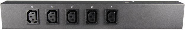
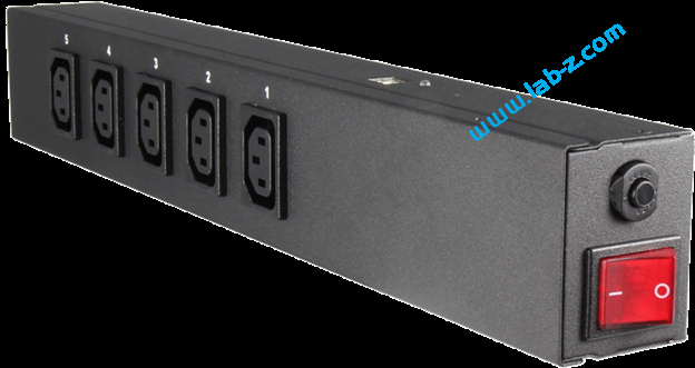
最近在研究一款USB控制的排插:BellWin 出品的带有USB接口的排插(USB Power Splitter)型号是:UP520US。它带有五个插孔,一个用于控制插孔供电的USB接口和一个供电开关。这款排插不是给家用设计的,上面的的插孔和插头都是专门为机房这种特别场合设计的,在家用环境中必须使用转接头才能工作。
电器特性如下【参考1】:
输入:220V,20A
输入频率:50/60Hz
功耗:5W
每一路最高可支持15A,五组最大支持输出20A
工作温度:0-25℃
接口:IEC60320 C13
认证:RoHS,IPC,CUS
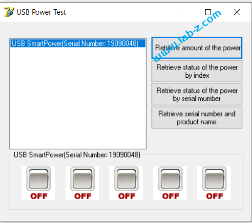
首先,测试一下它自带的控制程序。
用户可以通过下面的按钮控制每一路的开关。
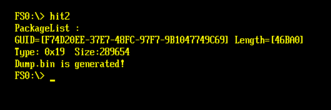
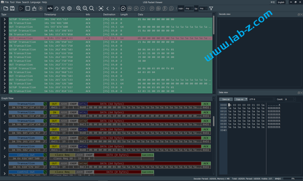
接下来,使用 USB Package Viewer 设备抓取USB 数据包。USB Package Viewer(简称UPV)是一款国产的USB数据逻辑分析仪,能够抓取从 Low Speed 到 High Speed的数据包。有兴趣的朋友可以在【参考2】看到之前我的开箱视频。这个仪器有一个比较大的优点是能够实时显示,这个在分析研究数据量不大的USB设备时非常有用。比如,上位机进行一个动作立刻能够在分析软件上看到数据,这样便于对应数据和操作。
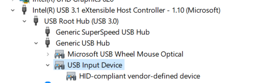
从设备管理器上也可以看出,这个设备使用USB HID 协议。
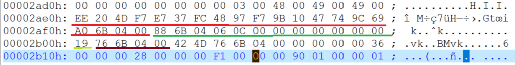
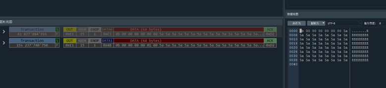
按下试验软件上的开关两次之后,在UPV中可以看到抓到了2个数据包:
经过多次试验,总结数据如下:
操作
抓到的数据,总长度64Bytes
Port1 设置为 OFF
0B 00 00 00 00 00 00 5A……5A
Port2 设置为OFF
0B 00 00 00 00 01 00 5A……5A
Port3 设置为OFF
0B 00 00 00 00 02 00 5A……5A
Port4 设置为OFF
0B 00 00 00 00 03 00 5A……5A
Port5 设置为OFF
0B 00 00 00 00 04 00 5A……5A
Port1 设置为 ON
0B 00 00 00 00 00 01 5A……5A
Port2 设置为ON
0B 00 00 00 00 01 01 5A……5A
Port3 设置为ON
0B 00 00 00 00 02 01 5A……5A
Port4 设置为ON
0B 00 00 00 00 03 01 5A……5A
Port5 设置为ON
0B 00 00 00 00 04 01 5A……5A
需要注意的是,上面的数据末端,使用0x5A 填充,实际上使用任意数据进行填充都可以, USB 排插以前面的有效数据为准。
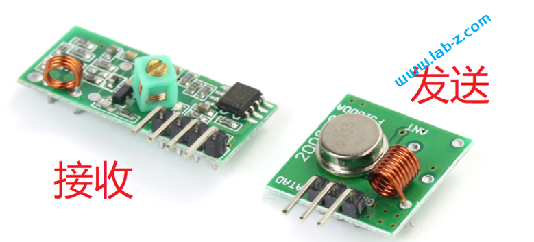
/* Format for protocol definitions:
* {pulselength, Sync bit, "0" bit, "1" bit, invertedSignal}
*
* pulselength: pulse length in microseconds, e.g. 350
* Sync bit: {1, 31} means 1 high pulse and 31 low pulses
* (perceived as a 31*pulselength long pulse, total length of sync bit is
* 32*pulselength microseconds), i.e:
* _
* | |_______________________________ (don't count the vertical bars)
* "0" bit: waveform for a data bit of value "0", {1, 3} means 1 high pulse
* and 3 low pulses, total length (1+3)*pulselength, i.e:
* _
* | |___
* "1" bit: waveform for a data bit of value "1", e.g. {3,1}:
* ___
* | |_
*
* These are combined to form Tri-State bits when sending or receiving codes.
*/
#if defined(ESP8266) || defined(ESP32)
static const VAR_ISR_ATTR RCSwitch::Protocol proto[] = {
#else
static const RCSwitch::Protocol PROGMEM proto[] = {
#endif
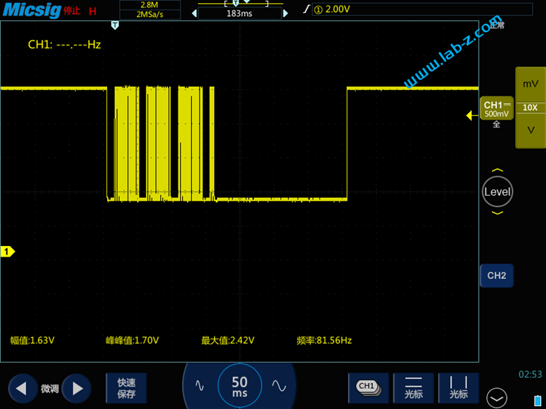
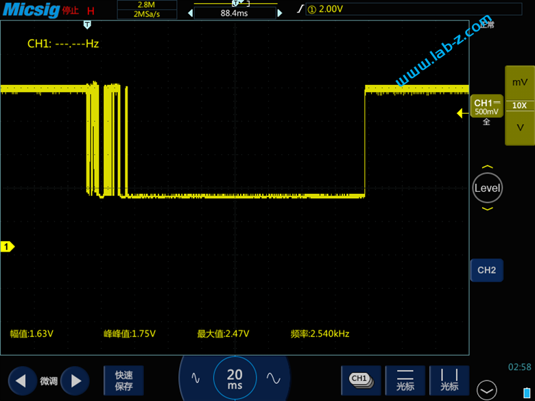
{ 350, { 1, 31 }, { 1, 3 }, { 3, 1 }, false }, // protocol 1
};
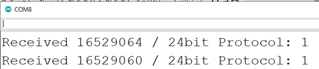
#include<RCSwitch.h>RCSwitch mySend =RCSwitch();voidsetup() {pinMode(2,INPUT_PULLUP);Serial.begin(115200);mySend.enableTransmit(17);// Optional set protocol (default is 1, will work for most outlets)mySend.setProtocol(1); }longintElsp=0;booleanOnFlag=false;voidloop() {if((millis()-Elsp>2000)&&(digitalRead(2)==HIGH)) {Serial.print("Fire");if(OnFlag) {// 开mySend.send(16529064, 24);Serial.println("Send on command");}else{// 关mySend.send(16529060, 24);Serial.println("Send off command");} OnFlag=!OnFlag;Elsp=millis();}}