Arduino 默认使用了 Timer0 【参考1】,在 \arduino-1.6.3\hardware\arduino\avr\cores\arduino\wiring.c 有
#if defined(__AVR_ATtiny24__) || defined(__AVR_ATtiny44__) || defined(__AVR_ATtiny84__)
ISR(TIM0_OVF_vect)
#else
ISR(TIMER0_OVF_vect)
#endif
{
	// copy these to local variables so they can be stored in registers
	// (volatile variables must be read from memory on every access)
	unsigned long m = timer0_millis;
	unsigned char f = timer0_fract;

	m += MILLIS_INC;
	f += FRACT_INC;
	if (f >= FRACT_MAX) {
		f -= FRACT_MAX;
		m += 1;
	}

	timer0_fract = f;
	timer0_millis = m;
	timer0_overflow_count++;
}
简单的说,设置Timer0 1ms触发一次,然后其中的计数器会自动加1。同样的文件中还能看到millis( ) micros() 和delay() 函数都用到这个计数值。所以有如下结论:
1. 如果修改了Timer0的计时频率,这些函数都会受到影响
2. 如果你关闭了Timer0,那么这些函数都会失效
3. 如果你是编写中断服务,进入你的服务程序之后,关闭了中断,那么不可以使用这些函数
我们尝试修改这个文件,插入翻转pin的代码,可以看到,示波器上一直显示电平有变化
#if defined(__AVR_ATtiny24__) || defined(__AVR_ATtiny44__) || defined(__AVR_ATtiny84__)
ISR(TIM0_OVF_vect)
#else
ISR(TIMER0_OVF_vect)
#endif
{
	// copy these to local variables so they can be stored in registers
	// (volatile variables must be read from memory on every access)
	unsigned long m = timer0_millis;
	unsigned char f = timer0_fract;

	m += MILLIS_INC;
	f += FRACT_INC;
	if (f >= FRACT_MAX) {
		f -= FRACT_MAX;
		m += 1;
	}

	timer0_fract = f;
	timer0_millis = m;
	timer0_overflow_count++;
	//LABZ_Debug_Start
	digitalWrite(9,LOW);
	digitalWrite(9,HIGH);
	digitalWrite(9,LOW);
	//LABZ_Debug_End
}
验证的代码非常简单:
void setup() {
  // put your setup code here, to run once:
  pinMode(9,OUTPUT);
}
void loop() {
 }
运行结果
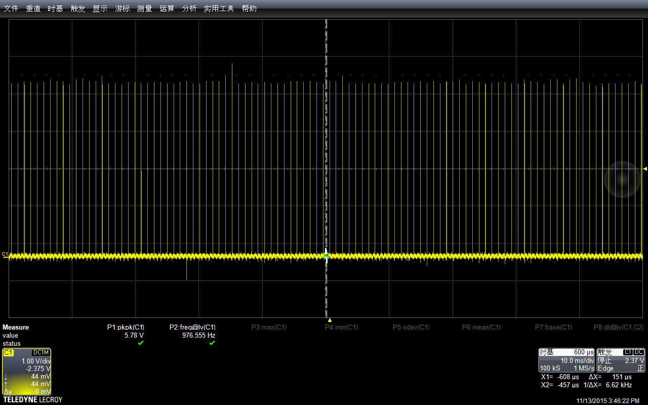
放大一些看,间隔在1ms左右,就是Timer0触发一次的时间

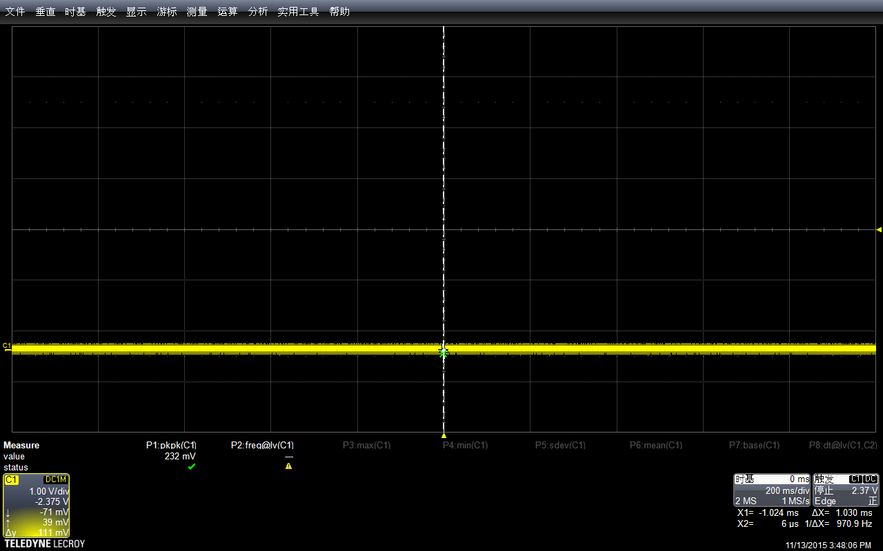
同样的程序我们在主程序中使用noInterrupts关掉中断【参考2】,显示出来始终为低电平,因为Timer0被关掉了,ISR中的代码永远不会跑到。
void setup() {
  // put your setup code here, to run once:
  pinMode(9,OUTPUT);
  noInterrupts();
}

void loop() {
  // put your main code here, to run repeatedly:

}
运行结果,始终为低电平
某些时候我们只需要关闭Timer0的中断,可以用屏蔽溢出中断的方法,设置TOIE0为0即可。
#define OutPin 8
#ifndef cbi
#define cbi(sfr, bit) (_SFR_BYTE(sfr) &= ~_BV(bit))
#endif
#ifndef sbi
#define sbi(sfr, bit) (_SFR_BYTE(sfr) |= _BV(bit))
#endif

void setup() {
  // put your setup code here, to run once:
  pinMode(OutPin,OUTPUT);
  digitalWrite(OutPin,LOW);
  cbi (TIMSK0, TOIE0);
}

void loop() {
  // put your main code here, to run repeatedly:

}
运行结果和上图没差别,一直未低
此外还可以通过关闭Timer0的source的方法【参考3】来关闭Timer0.具体只要设置 CS00==CS01==CS02==0 即可。
#define OutPin 9

void setup() {
  // put your setup code here, to run once:
  pinMode(OutPin,OUTPUT);
  digitalWrite(OutPin,LOW);

}

void loop() {
  delay(1000);
  bitWrite(TCCR0B, CS00, 0);
  bitWrite(TCCR0B, CS01, 0);
  bitWrite(TCCR0B, CS02, 0);
  delayMicroseconds(10000);
  digitalWrite(OutPin,HIGH);
}
进入 loop函数之后 delay 1s 持续有中断产生,之后关闭了中断就出现一直为低的情况,接下来是10ms的delay,最后再拉高(这样只是为了让波形清晰可辩)。
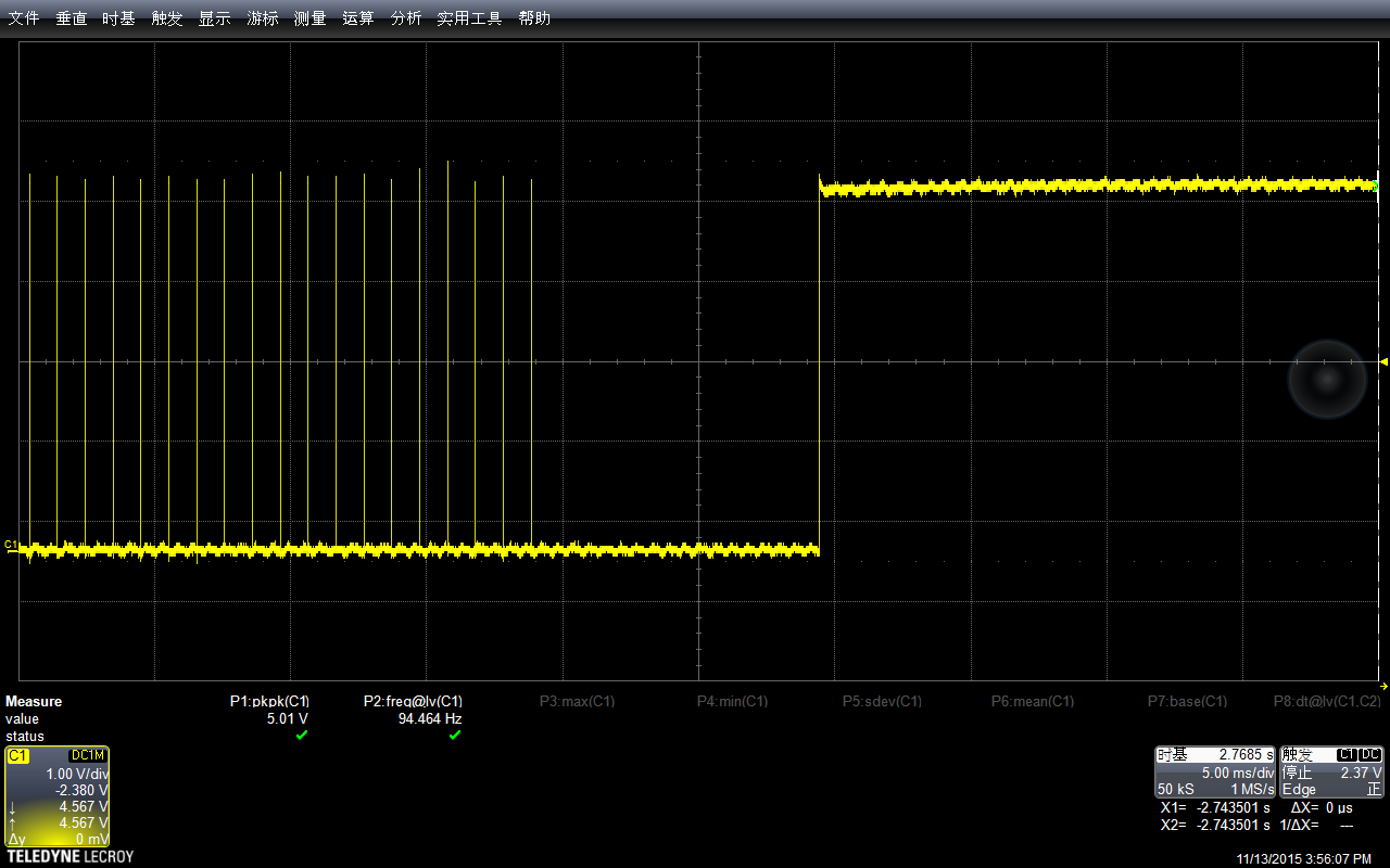
放大一点可以看到,中间有间隔是10539ms.
特别注意:上述代码中,如果我将delayMicroseconds换成 Delay,那么看到的波形将会是一直为低。读者可以思考一下原因。
参考:
1. http://letsmakerobots.com/node/28278 Arduino 101: Timers and Interrupts
2.\arduino-1.6.3\hardware\arduino\avr\cores\arduino\Arduino.h
#define interrupts() sei()
#define noInterrupts() cli()
3. https://arduinodiy.wordpress.com/2012/02/28/timer-interrupts/
Clock Select bit description
CS12 CS11 CS10 Description
0 0 0 No clock source (Timer/Counter stopped)
0 0 1 clki/o/1 (No prescaling)
0 1 0 clki/o/8 (From Prescaler)
0 1 1 clki/o/64 (From Prescaler)
1 0 0 clki/o/256 (From Prescaler)
1 0 1 clki/o/1024 (From Prescaler)
1 1 0 External clock source on T1 pin. Clock on falling edge
1 1 1 External clock source on T1 pin. Clock on rising edge