TPS63802 升降压芯片模块测试

TPS63802DLAR 是 TI 推出降压/升压转换器。

• 输入电压范围:1.3V 至 5.5V – 器件启动时输入电压大于 1.8V

• 输出电压范围:1.8V 至 5.2V(可调节),计算公式 Vout=(R1/R2+1)*0.5V

• VI ≥ 2.3V、VO = 3.3V 时,输出电流为 2A

这里使用这个芯片制作一个模块,对于外部输入的 1.8-5.5V 的电压转化为 3.3V。

焊接之后如下

接下来对模块进行测试:

1.7V输入时,模块不工作

1.8V时开始工作,输出3.3V

2.4V时输出3.3V

3.4V时输出3.3V

4.4V时输出3.3V

5.4V时输出3.3V

可见,这个芯片非常适合配合 3.7V 充电电池使用。

模块的电路图和PCB下载(立创标准版)

C# 程序:统计文本文件中未曾出现的 ASCII

一段简单的代码,找到给定的文本中哪个 ASCII 字符没有出现过

using System;
using System.Collections.Generic;
using System.Linq;
using System.Text;
using System.Threading.Tasks;
using System.IO;

namespace FilterAscii
{
    class Program
    {
        static void Main(string[] args)
        {
            if (args.Length == 0)
            {
                Console.WriteLine("Usage: AsciiCharCounter <filename>");
                return;
            }

            string filename = args[0];
            if (!File.Exists(filename))
            {
                Console.WriteLine($"File not found: {filename}");
                return;
            }

            bool[] charPresence = new bool[128];
            foreach (char c in File.ReadAllText(filename))
            {
                if (c < 128) charPresence[c] = true;
            }

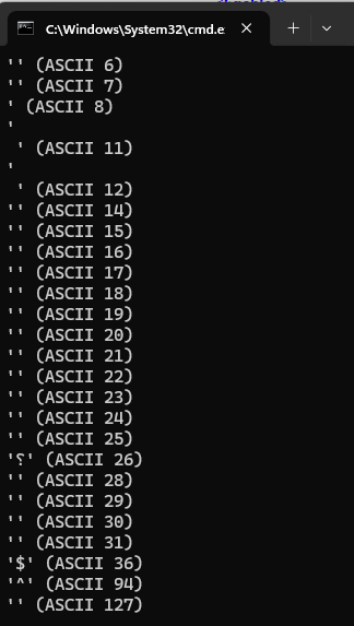
            Console.WriteLine("Missing ASCII characters:");
            for (int i = 0; i < 128; i++)
            {
                if (!charPresence[i])
                {
                    Console.WriteLine($"'{(char)i}' (ASCII {i})");
                }
            }
        }
    }
}

我用这个工具分析一个Debug BIOS 串口输出结果如下,没有出现过的大部分 ASCII 都是不可见的,只有 $ 和 ^ 这两个可见的没有输出过

Arduino中ESP32 P4 中一次性设置多个 GPIO的方法

一般情况下我们可以用过 digitalWrite() 在 Arduino 中设置 GPIO 的 HIGH/LOW, 但是这种方法非常耗时。这里给出一种可以一次性设置多个 GPIO 的方法:

在 C:\Users\USERNAME\AppData\Local\Arduino15\packages\esp32\tools\esp32-arduino-libs\idf-release_v5.4-858a988d-v1-cn\esp32p4\include\soc\esp32p4\register\soc\gpio_struct.h 有如下定义:

extern gpio_dev_t GPIO;

typedef struct gpio_dev_t {
    volatile gpio_bt_select_reg_t bt_select;
    volatile gpio_out_reg_t out;
    volatile gpio_out_w1ts_reg_t out_w1ts;
    volatile gpio_out_w1tc_reg_t out_w1tc;
    volatile gpio_out1_reg_t out1;
    volatile gpio_out1_w1ts_reg_t out1_w1ts;
    volatile gpio_out1_w1tc_reg_t out1_w1tc;
    uint32_t reserved_01c;
    volatile gpio_enable_reg_t enable;
    volatile gpio_enable_w1ts_reg_t enable_w1ts;
    volatile gpio_enable_w1tc_reg_t enable_w1tc;
    volatile gpio_enable1_reg_t enable1;
    volatile gpio_enable1_w1ts_reg_t enable1_w1ts;
    volatile gpio_enable1_w1tc_reg_t enable1_w1tc;
    volatile gpio_strap_reg_t strap;
    volatile gpio_in_reg_t in;
    volatile gpio_in1_reg_t in1;
    volatile gpio_status_reg_t status;
    volatile gpio_status_w1ts_reg_t status_w1ts;
    volatile gpio_status_w1tc_reg_t status_w1tc;
    volatile gpio_status1_reg_t status1;
    volatile gpio_status1_w1ts_reg_t status1_w1ts;
    volatile gpio_status1_w1tc_reg_t status1_w1tc;
    volatile gpio_intr_0_reg_t intr_0;
    volatile gpio_intr1_0_reg_t intr1_0;
    volatile gpio_intr_1_reg_t intr_1;
    volatile gpio_intr1_1_reg_t intr1_1;
    volatile gpio_status_next_reg_t status_next;
    volatile gpio_status_next1_reg_t status_next1;
    volatile gpio_pin_reg_t pin[57];
    volatile gpio_func_in_sel_cfg_reg_t func_in_sel_cfg[256]; /* func0-func255: reserved for func0, 46, 67, 72, 73, 79, 81, 82, 84, 85, 87, 88, 115, 116, 119-125, 157, 204-213 */
    volatile gpio_func_out_sel_cfg_reg_t func_out_sel_cfg[57];
    volatile gpio_intr_2_reg_t intr_2;
    volatile gpio_intr1_2_reg_t intr1_2;
    volatile gpio_intr_3_reg_t intr_3;
    volatile gpio_intr1_3_reg_t intr1_3;
    volatile gpio_clock_gate_reg_t clock_gate;
    uint32_t reserved_650[44];
    volatile gpio_int_raw_reg_t int_raw;
    volatile gpio_int_st_reg_t int_st;
    volatile gpio_int_ena_reg_t int_ena;
    volatile gpio_int_clr_reg_t int_clr;
    volatile gpio_zero_det_filter_cnt_reg_t zero_det_filter_cnt[2];
    volatile gpio_send_seq_reg_t send_seq;
    volatile gpio_recive_seq_reg_t recive_seq;
    volatile gpio_bistin_sel_reg_t bistin_sel;
    volatile gpio_bist_ctrl_reg_t bist_ctrl;
    uint32_t reserved_728[53];
    volatile gpio_date_reg_t date;
} gpio_dev_t;

其中的out_w1ts 和 out_w1tc 可以用来一次性设置多个 GPIO 为高或者为低。

测试代码:

#include "soc/gpio_struct.h" // GPIO

void setup() {
   pinMode(7,OUTPUT);pinMode(8,OUTPUT);
   pinMode(30,OUTPUT);pinMode(32,OUTPUT);pinMode(33,OUTPUT);pinMode(49,OUTPUT);
   pinMode(50,OUTPUT);pinMode(52,OUTPUT);
   digitalWrite(7,LOW);digitalWrite(8,LOW);
   digitalWrite(30,LOW);digitalWrite(32,LOW);digitalWrite(33,LOW);digitalWrite(49,LOW);
   digitalWrite(50,LOW);digitalWrite(52,LOW);

}

void loop() {
    GPIO.out_w1ts.val = (1<<30)|(1<<8)|(1<<7); 
    GPIO.out1_w1ts.val=(1<<(33-32))|(1<<(32-32))|(1<<(52-32))|(1<<(49-32))|(1<<(50-32));
    GPIO.out_w1tc.val = (1<<30)|(1<<8)|(1<<7); 
    GPIO.out1_w1tc.val=(1<<(33-32))|(1<<(32-32))|(1<<(52-32))|(1<<(49-32))|(1<<(50-32));
    delay(1000);
}

硬件上GPIO33, 32, 30, 8, 7, 52, 49, 50分别连接到逻辑分析的4-11通道。

其中的 GPIO 初始化使用 Arduino 代码来完成,GPIO 的设置直接使用位操作。超过31的GPIO要在out1_w1ts和out1_w1tc上设置。

最终抓到的结果可以从下面看到:

参考:

1.https://github.com/maarten-pennings/howto/blob/main/esp32-fast-gpio/esp32-fast-gpio.md

Basic AML Debugging

The AMLI Debugger supports two types of specialized commands: AMLI Debugger extensions and AMLI Debugger commands.

When you are performing AML debugging, you should carefully distinguish between two different kinds of prompts that will appear in the Debugger Command window:

  • When you see the kd> prompt, you are controlling the kernel debugger. All the standard kernel debugger commands and extensions are available. In addition, the AMLI Debugger extensions are also available. In Windows 2000, these extensions have a syntax of !acpikd.amli command. In Windows XP and later versions of Windows, these extensions have a syntax of !amli command. The AMLI Debugger commands are not available in this mode.
  • When you see the AMLI(? for help)-> prompt, you are controlling the AMLI Debugger. (When you are using WinDbg, this prompt will appear in the top pane of the Debugger Command window, and an Input> prompt will appear in the bottom pane.) From this prompt, you can enter any AMLI Debugger command. You can also enter any AMLI Debugger extension; these extensions should not be prefixed with !amli. The standard kernel debugging commands are not available in this mode.
  • When you see no prompt at all, the target computer is running.

At the beginning of any debugging session, you should set your AMLI Debugger options with the !amli set extension. The verboseontraceon, and errbrkon options are also very useful. When your target computer is running Windows XP or later, you should always activate the spewon option. See the extension reference page for details.

There are several ways for the AMLI Debugger to become active:

  • If a breakpoint in AML code is encountered, ACPI will break into the AMLI Debugger.
  • If a serious error or exception occurs within AML code (such as an int 3), ACPI will break into the AMLI Debugger.
  • If the errbrkon option has been set, any AML error will cause ACPI to break into the AMLI Debugger.
  • If you want to deliberately break into the AMLI Debugger, use the !amli debugger extension and then the g (Go) command. The next time any AML code is executed by the interpreter, the AMLI Debugger will take over.

When you are at the AMLI Debugger prompt, you can type q to return to the kernel debugger, or type g to resume normal execution.

The following extensions are especially useful for AML debugging:

  • The !amli dns extension displays the ACPI namespace for a particular object, the namespace tree subordinate to that object, or even the entire namespace tree. This command is especially useful in determining what a particular namespace object is — whether it is a method, a fieldunit, a device, or another type of object.
  • The !amli find extension takes the name of any namespace object and returns its full path.
  • The !amli u extension unassembles AML code.
  • The !amli lc extension displays brief information about all active ACPI contexts.
  • The !amli r extension displays detailed information about the current context of the interpreter. This is useful when the AMLI Debugger prompt appears after an error is detected.
  • Breakpoints can be set and controlled within AML code. Use !amli bp to set a breakpoint, !amli bc to clear a breakpoint, !amli bd to disable a breakpoint, !amli be to re-enable a breakpoint, and !amli bl to list all breakpoints.
  • The AMLI Debugger is able to run, step, and trace through AML code. Use the runp, and t commands to perform these actions.

For a full list of extensions and commands, see Using AMLI Debugger Extensions and Using AMLI Debugger Commands .

CH397 的 IPXE 启动

最近测试了一下 WCH 出品的 CH397 USB 网卡(百兆)网络启动功能,通过网络成功的启动到WinPE 环境。通过这样的方式用户可以方便的进行系统安装和维护。

除此之外,该IPXE启动方案支持 WCH USB网卡全系列产品:CH398(USB3.0千兆网卡) 、CH397、CH339(七端口路多功能HUB)、CH336(四端口HUB)。

本文记录一下操作过程。测试环境是2台电脑(网线直连,没有通过路由器之类),本次实验使用到的软件可以在文章后面下载到,解压在主机端的 CH397PXE 目录下即可

1.一台作为主机,主机端需要手工指定一个 IP地址,这里使用  192.168.50.2

2.PXE Server选用的是 Tiny PXE Server,来自【参考1】,除了TFTP、HTTP服务它还能提供 DHCP 功能。

3.PXE Server 配置如下,Boot File 选择C:\CH397PXE\Menu.ipxe

上述配置完成后,点击Tiny PXE Server 的 Online 按钮即可启动

1.目标机上使用一个 FAT32 U盘作为启动盘,将C:\CH397PXE\ Ch397_ipxe.efi 改名为 BootX64.efi 后放在这个U盘的 EFI\Boot\ 目录下

2.在目标机上启动这个U盘,自动进入 IPXE

3.进入一个选择菜单,其中的内容是我们上面提到的 menu.ipxe 中定义的

4.开始加载Win10 的 WinPE 镜像

5.最终启动进入 WinPE 环境,进去之后加载 CH397的驱动,还可以看到通过 DHCP自动给当前设备分配了 IP 地址。

本文提到的 Ch397_ipxe.efi(官方 IPXE没有CH397支持,这是WCH官方定制的) 可以在这里下载。

测试使用的 Tiny PXE Server 和修改后的 Win10 可以在这里下载。

http://a78231029.gs2.cosfiles.com/d/ty-2501/LABZ/ch397PXE.7z

工作的测试视频

参考:

  1. https://github.com/erwan2212/tinypxeserver
  2. https://zhuanlan.zhihu.com/p/343569176  UEFI开发探索50 – UEFI与网络2
  3. https://www.lab-z.com/vt/

搜集到的老版本 IASL

在一些情况下,我们需要老版本的 iasl.exe 来处理ACPI,这里整理了一下,有需要的朋友可以下载:

iasl20051117.exe
iasl20100121.exe
iasl20100806.exe
iasl20120111-32.exe
iasl20121220-32.exe
iasl20130117-32.exe
iasl20160729-32.exe
iasl20200717.exe
iasl20210331.exe
iasl20210930.exe
iasl20230628.exe
待补充

在这里可以下载上述集合,同时欢迎提供你手上的老版本方便他人使用。

ESP32 P4 Arduino GPIO 最快翻转速度测试

测试代码如下:

#include <arduino.h>
#include "soc/gpio_struct.h" // GPIO

void setup() {
  pinMode(20,OUTPUT);
}

void loop() {
  GPIO.out_w1ts.val = 1<<20;
  GPIO.out_w1tc.val = 1<<20;
  GPIO.out_w1ts.val = 1<<20;
  GPIO.out_w1tc.val = 1<<20;
  GPIO.out_w1ts.val = 1<<20;  
  delay(100);
}

可以看到翻转以 100ms 为间隔

放大可以看到从低->高或者高->低,最少需要 250ns