最近工作需要在 UEFI Shell 下Check EC Ram 的设定,发现手上只有 Windows 下的读取工具(RW Everything)。于是研究了一下如何在Shell 读取 EC Ram。
根据【参考1】读取的流程如下:
Port 66 Commands
There are also some EC commands that use ports 0x66 and 0x62. Some of these are standard ACPI commands as defined in the external ACPI spec, others are custom.
The port 66 protocol is essentially the standard ACPI EC interface protocol.
1. Wait for port66.IBF = 0
2. Write command byte to port 66.
3. For each outgoing data or address byte:
3a. Wait for port66.IBF = 0
3b. Write data or address byte to port 62.
4. For each incoming data byte:
4a. Wait for port66.OBF = 1
4b. Read data byte from port 62.
5. If the command requires no data or address bytes, you can determine when the command was accepted/executed by waiting for port66.IBF=0.
同时 ACPI 定义的通用 Command如下:
ACPI-defined port 66 commands
0x80 Read EC (write 0x80 to port 66, write address byte to port 62, read data byte from port 62)
0x81 Write EC (write 0x81 to port 66, write address byte to port 62, write data byte to port 62)
0x82 Burst Enable (write 0x82 to port 66, read data byte from port 62 – the data byte is “burst ACK”, value 0x90)
0x83 Burst Disable (write 0x83 to port 66, wait for port66.IBF=0)
0x84 Query EC (i.e. read SCI event queue) (write 0x84 to port 66, read data byte from port 62). When the data byte is 0, it means that the SCI event queue is empty.
最终根据上述资料,编写一个 Application 如下:
#include  <Uefi.h>
#include  <Library/UefiLib.h>
#include  <Library/ShellCEntryLib.h>
#include  <Library/IoLib.h>

extern  EFI_SYSTEM_TABLE    *gST;
extern  EFI_BOOT_SERVICES   *gBS;

#define TIMEOUT         0xFFFF
#define ECCOMMAND       0x66
#define ECSTATUS        0x66
#define ECDATA          0x62
#define EC_S_OBF           BIT0
#define EC_S_IBF           BIT1
#define ECREADCMD          0x80

UINT8   MemBuffer[16][16];

void   WaitIBF() {
  UINT32 Status;
  UINTN Count;

  Count = 0;
  Status = 0;

  Status = IoRead8 (ECSTATUS);
  while (((Status & EC_S_IBF) != 0)||(Count>TIMEOUT)) {
    Status = IoRead8 (ECSTATUS);
    Count++;
  }
}

void    WaitOBF() {
  UINT32 Status;
  UINTN Count;

  Count = 0;
  Status = 0;

  Status = IoRead8 (ECSTATUS);
  while (((Status & EC_S_OBF) == 0)||(Count>TIMEOUT)) {
    Status = IoRead8 (ECSTATUS);
    Count++;
  }
}

UINT8 ReadECRam(UINT8 Index) {
  WaitIBF();               //1
  IoWrite8(ECCOMMAND,0x80);//2
  WaitIBF();               //3a
  IoWrite8(ECDATA, Index); //3b
  WaitOBF();               //4a
  return IoRead8(ECDATA); //4b
}

void GetData()
{
        UINT8   i,j;
        for (i=0;i<16;i++)
          for (j=0;j<16;j++) {
             MemBuffer[i][j]=ReadECRam(i*16+j);
          }
}
void ShowData()
{
        UINT8   i,j;
        Print(L"    ");
        for (i=0;i<16;i++) Print(L"%02X ",i);
        Print(L"\n");
        for (i=0;i<16;i++) {
                Print(L"%02X: ",i);
           for (j=0;j<16;j++) {
                Print(L"%02X ",MemBuffer[i][j]);
           }
           Print(L"\n");
        }
        Print(L"\n");
}
/***
  Print a welcoming message.

  Establishes the main structure of the application.

  @retval  0         The application exited normally.
  @retval  Other     An error occurred.
***/
INTN
EFIAPI
ShellAppMain (
  IN UINTN Argc,
  IN CHAR16 **Argv
  )
{
  EFI_INPUT_KEY         Key;

  Key.ScanCode=SCAN_NULL;
  while (SCAN_UP!=Key.ScanCode)
    {
        gST->ConOut->ClearScreen(gST->ConOut);
        GetData();
        ShowData();
        gST -> ConIn -> ReadKeyStroke(gST->ConIn,&Key);
        Print(L"Press Arrow-Up to exit\n");
        gBS->Stall(1000000UL);
    }

    return(0);
}
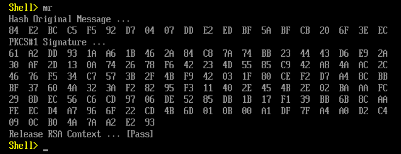
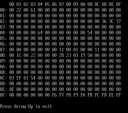
在实体机上运行结果如下(按向上键退出):
源代码和Application(X64)下载:
参考:
1. http://wiki.laptop.org/go/Ec_specification