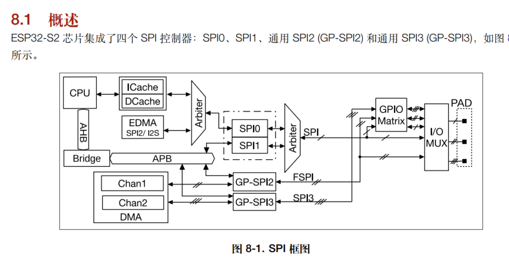
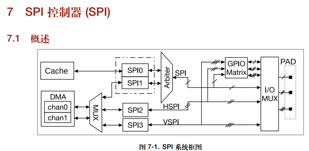
打开ESP32-S2 技术参考手册 (“esp32-s2_technical_reference_manual_cn”),可以看到下图:
ESP32 S2的Arduino 环境对于 SPI 的定义是有问题的。

对于 S2 这个芯片来说,有四个 SPI,其中“SPI0 和 SPI1 仅供内部使用,通过仲裁器共享 SPI 信号总线”。因此,对于用户来说,只能使用 FSPI(GP-SPI2)和SPI3(GP-SPI3)。对比之前的 ESP32:

同样的有4个 SPI,其中“SPI0控制器作为 cache 访问外部存储单元接口使用” ,因此用户可以使用 SPI1-3,其中 SPI2 又称作 HSPI ,SPI3又称作 VPSI。其中的 HSPI 和 VSPI 只是一个代号,并不表示 High Speed SPI 值了的。
对比二者,再次强调S2 只有 FSPI 和 SPI3。但是在\Arduino15\packages\esp32\hardware\esp32\2.0.1\cores\esp32\esp32-hal-spi.h 中有如下定义:
#if CONFIG_IDF_TARGET_ESP32C3
#define FSPI  0
#define HSPI  1
#else
#define FSPI  1 //SPI bus attached to the flash (can use the same data lines but different SS)
#define HSPI  2 //SPI bus normally mapped to pins 12 - 15, but can be matrixed to any pins
#if CONFIG_IDF_TARGET_ESP32
#define VSPI  3 //SPI bus normally attached to pins 5, 18, 19 and 23, but can be matrixed to any pins
#endif
#endif
这样导致在你编写的 ESP32 S2 代码中 FSPI=1 HSPI=2, 欢聚话说 FSPI 是 SPI1, HSPI 才是 GP-SPI2。这会导致之前能够正常运行在ESP32的代码移植到 S2 之后SPI 无法工作(想确认这一点最简单的方法是示波器测量 SPI SCLK 信号)。
此外,SPI.cpp定义的 SPI实际上是 SPI1,这个在 S2 上根本无法工作。
#if CONFIG_IDF_TARGET_ESP32
SPIClass SPI(VSPI);
#else
SPIClass SPI(FSPI);
#endif
如果你的代码直接使用 SPI,那么无比将上面的代码修改为 SPIClass SPI(HSPI);。
第二个坑是关于 SPI 引脚分配的,同样在 SPI.cpp 中有如下定义,如果你没有给定 SPI 的引脚,那么默认分配的都是 -1 Pin:
    if(sck == -1 && miso == -1 && mosi == -1 && ss == -1) {
#if CONFIG_IDF_TARGET_ESP32S2
        _sck = (_spi_num == FSPI) ? SCK : -1;
        _miso = (_spi_num == FSPI) ? MISO : -1;
        _mosi = (_spi_num == FSPI) ? MOSI : -1;
        _ss = (_spi_num == FSPI) ? SS : -1;
这个在代码中可以使用 Serial.print(hspi->pinSS()); 进行检查。最后是一个我这边测试过,ESP32 S2 工作正常的 SPI 例子。使用 GP-SPI2 ,定义SCLK = 14, MISO = 12, MOSI = 13, SS = 15.
#include <SPI.h>

static const int spiClk = 40000000;

SPIClass * hspi = NULL;

void setup() {
  Serial.begin(115200);
  //initialise two instances of the SPIClass attached to VSPI and HSPI respectively
  hspi = new SPIClass(HSPI);

  //initialise hspi with default pins
  //SCLK = 14, MISO = 12, MOSI = 13, SS = 15
  hspi->begin(10,12,11,13);

  //set up slave select pins as outputs as the Arduino API
  //doesn't handle automatically pulling SS low
  pinMode(hspi->pinSS(), OUTPUT); //HSPI SS

}

// the loop function runs over and over again until power down or reset
void loop() {

  spiCommand(hspi, 0b11001100);

  Serial.print(MISO);Serial.print(" ");
  Serial.print(MOSI);Serial.print(" ");
  Serial.print(SCK);Serial.print(" ");
  Serial.print(SS);Serial.print(" ");
  Serial.print(HSPI);Serial.print(" ");
  Serial.print(FSPI);Serial.print(" ");
  Serial.print(hspi->pinSS());Serial.println(" ");

  delay(2000);
}

void spiCommand(SPIClass *spi, byte data) {
  //use it as you would the regular arduino SPI API
  spi->beginTransaction(SPISettings(spiClk, MSBFIRST, SPI_MODE0));
  digitalWrite(spi->pinSS(), LOW); //pull SS slow to prep other end for transfer
  spi->transfer(data);
  digitalWrite(spi->pinSS(), HIGH); //pull ss high to signify end of data transfer
  spi->endTransaction();
}
=============================================================
2022年5月10日更新,在 2.0.1 上实验完全不修改 Arduino 相关文件,完全使用默认配置,下面的代码将使用IO34/35/37/36 分别作为 SS/MOSI/MISO/SCK (示波器验证过)
static const uint8_t SS = 34;
static const uint8_t MOSI = 35;
static const uint8_t MISO = 37;
static const uint8_t SCK = 36;
上述定义来自C:\Users\NAME\AppData\Local\Arduino15\packages\esp32\hardware\esp32\2.0.1\variants\esp32s2\pins_arduino.h
#include <SPI.h>
static const int spiClk = 40000000;
void setup() {
  Serial.begin(115200);
  SPI.begin();
}

void loop() {
  spiCommand(&SPI, 0b11001100);
  Serial.print(MISO);Serial.print(" ");
  Serial.print(MOSI);Serial.print(" ");
  Serial.print(SCK);Serial.print(" ");
  Serial.print(SS);Serial.print(" ");
  Serial.print(HSPI);Serial.print(" ");
  Serial.print(FSPI);Serial.println(" ");

  delay(200);

}


void spiCommand(SPIClass *spi, byte data) {

  //use it as you would the regular arduino SPI API

  spi->beginTransaction(SPISettings(spiClk, MSBFIRST, SPI_MODE0));

  digitalWrite(spi->pinSS(), LOW); //pull SS slow to prep other end for transfer

  spi->transfer(data);

  digitalWrite(spi->pinSS(), HIGH); //pull ss high to signify end of data transfer

  spi->endTransaction();

}