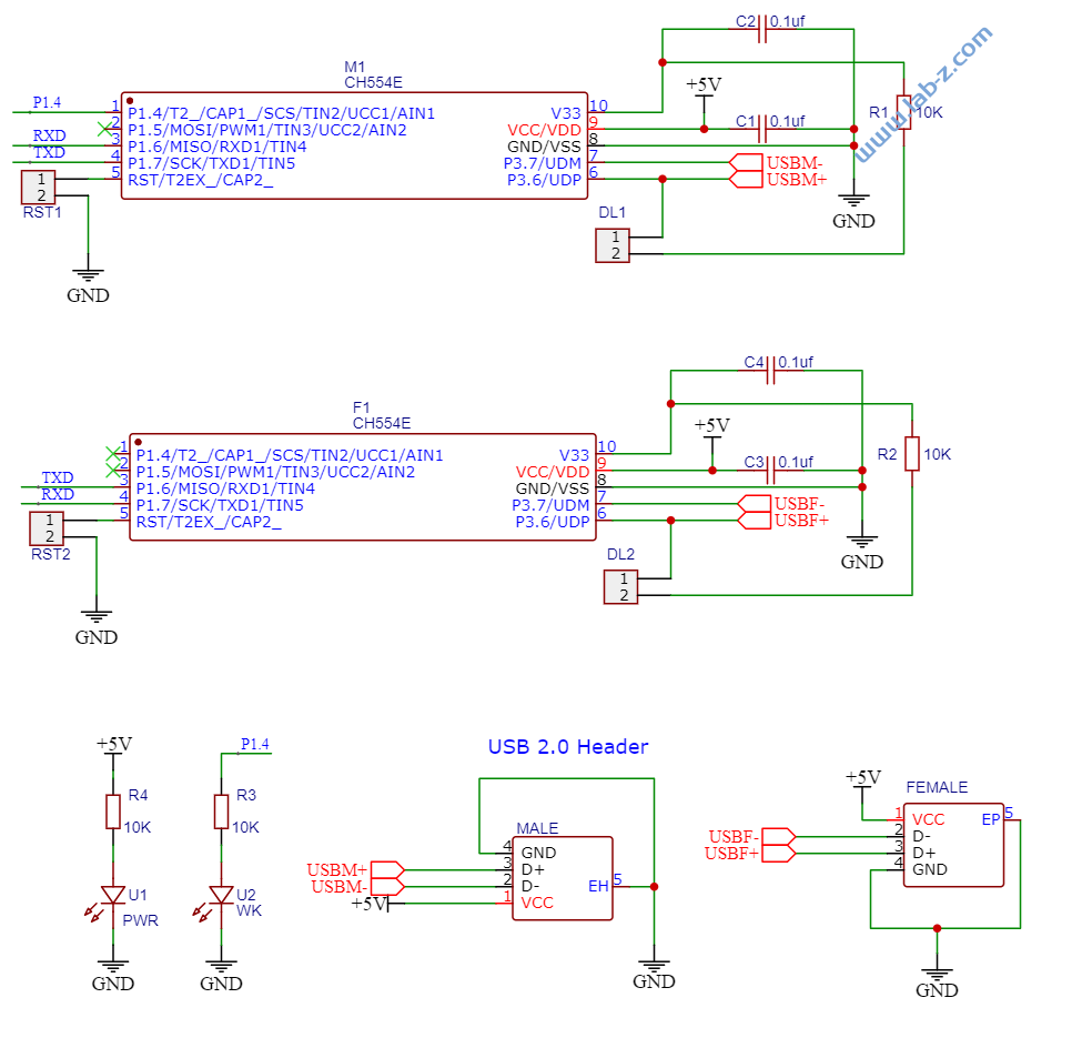
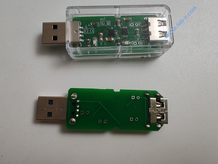
最近设计了一个 USB 转USB 设备,它带有一个USB公头和一个USB母头,可以读取一个USB 设备发出来的数据,然后转换为另外的数据。
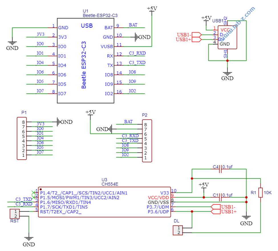
首先是硬件设计,使用了2个 CH554e芯片,这个芯片能够实现 USB Host和Device,二者通过串口进行通讯。这款芯片是南京WCH出品的,最高支持 24Mhz主频内置,16K程序存储器ROM和256字节内部iRAM以及1K 字节片内xRAM。Ch554e 是最小的封装形式,MOP10方便焊接。
硬件设计比较简单,2个5V供电的Ch554的最小系统,中间通过串口连接。
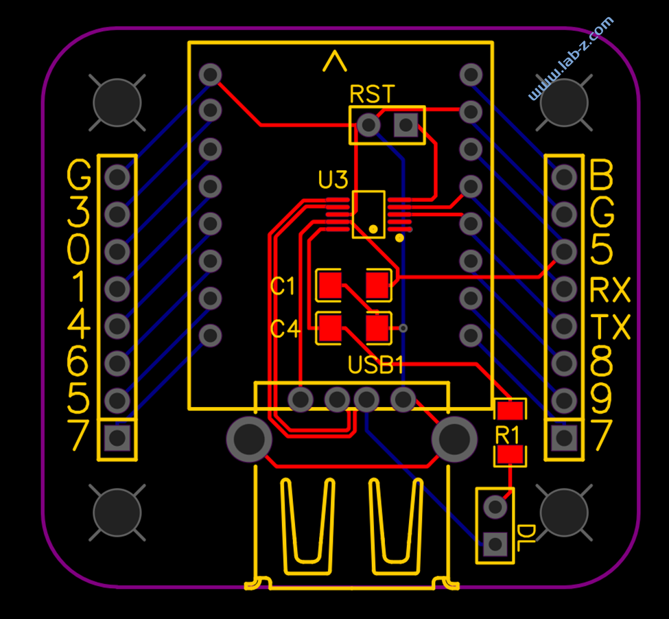
PCB 设计如下:
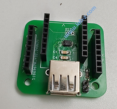
这样的设计刚好能够放入淘宝购买的透明外壳中。
两个 Ch554分别写入不同的固件。其中USB母头连接Ch554的需要写入 Keil编译的代码,用于实现 USB Host 功能。解析后的HID 数据会按照 Ch9350 格式通过串口输出,有兴趣的朋友可以在【参考1】看到实现。
USB 公头连接的Ch554代码使用 Arduino 进行编译。实现的功能是检测通过串口获得数据是否包含 wasd 这几个按键,如果有的话就转为对应的鼠标移动操作:
#ifndef USER_USB_RAM
//#error "This example needs to be compiled with a USER USB setting"
#endif

#include "src/userUsbHidKeyboardMouse/USBHIDKeyboardMouse.h"

#define DEBUGMODE 0

void setup() {
  // 串口通讯
  Serial1_begin(500000);
  USBInit();
  pinMode(14, OUTPUT);
  digitalWrite(14, LOW);
}

boolean FindKey(byte s, byte *p, byte len) {
  for (byte i = 0; i < len; i++) {
    if (p[i] == s) {
      return true;
    }
  }
  return false;
}
void loop() {
  //根据 CH9350 Spec 每次最多输出 72Bytes
  byte Data[72];
  byte CounterLast = Serial1_available();
  byte CounterCurrent = 0;

  // 如果当前串口有数据
  if (CounterLast != 0) {
    // 进行简单测试,如果当前还在传输数据那么持续接收
    while (CounterCurrent != CounterLast) {
      CounterLast = Serial1_available();
      delayMicroseconds(500);
      CounterCurrent = Serial1_available();
    }
  }

  if (CounterCurrent > 0) {
    // 一次性将数据收取下来
    //Serial1_readBytes(Data, CounterCurrent);
    for (byte i = 0; i < CounterCurrent; i++) {
      Data[i] = Serial1_read();
      //  USBSerial_print_ub(Data[i], 16);
    }

    unsigned int i = 0;
    unsigned int Length;
    while (i < CounterCurrent) {
      // 识别帧头
      if ((Data[i] == 0x57) && (Data[i + 1] == 0xAB)) {
        // 有效键值帧
        if (Data[i + 2] == 0x88) {
          // 获得数据长度
          Length = Data[i + 3];
          //如果是键盘
          if (Data[i + 4] == 0x10) {
            digitalWrite(14, HIGH);
            if (DEBUGMODE) {
              for (int j = 3; j < Length - 2; j++) {
                USBSerial_print_ub(Data[i + 3  + j], 16);
              }
              USBSerial_println_only();
            }
            if (FindKey(0x1A, Data, Length) == true) { // 'w'
              Mouse_move(0, -100);
            }
            if (FindKey(0x16, Data, Length) == true) { // 's'
              Mouse_move(0, 100);
            }
            if (FindKey(0x04, Data, Length) == true) { // 'a'
              Mouse_move(-100,0);
            }
            if (FindKey(0x07, Data, Length) == true) { // 'd'
              Mouse_move(100,0);
            }
            digitalWrite(14, LOW);
          } //if (Data[i + 4] == 0x10) {
        }
        i = i + 3 + Length;
      }
      i++;
    } // while (i < Counter)
  }
}
通过串口烧录,短接 DL1 或者 DL2 接口,插入 Windows主机后,设备管理器中会出现新的设备,然后使用 wchispstudio 即可烧写。对于USB Host 对应的Ch554需要一个 USB 公头转公头来实现转为USB公头然后进行烧写。
参考:
本文提到的完整代码下载:
1.模拟键盘的代码(Arduino)
2. USB Host 代码