正经的 Arduino Leonardo 上面有四个LED(DFrobot 的Leonardo&XBEE V1.2 上面有5个LED)。长得是下面这个样子:
对照电路图 LED 连接如下:
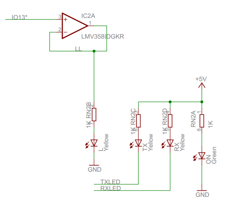
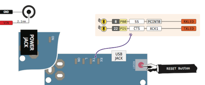
LED 控制Pin 说明
L D13 (PC7) GPIO 控制
TX PD5 USB发送数据亮
RX PB0 USB接收数据亮
ON 5V 上电就亮
初始化在 \arduino-1.8.4\hardware\arduino\avr\cores\arduino\USBCore.cpp 有定义
void USBDevice_::attach()
{
	_usbConfiguration = 0;
	_usbCurrentStatus = 0;
	_usbSuspendState = 0;
	USB_ClockEnable();

	UDINT &= ~((1<<WAKEUPI) | (1<<SUSPI)); // clear already pending WAKEUP / SUSPEND requests
	UDIEN = (1<<EORSTE) | (1<<SOFE) | (1<<SUSPE);	// Enable interrupts for EOR (End of Reset), SOF (start of frame) and SUSPEND

	TX_RX_LED_INIT;

#if MAGIC_KEY_POS != (RAMEND-1)
	if (pgm_read_word(FLASHEND - 1) == NEW_LUFA_SIGNATURE) {
		_updatedLUFAbootloader = true;
	}
#endif
}
其中的 一些宏定义在 \arduino-1.8.4\hardware\arduino\avr\variants\leonardo\pins_arduino.h
#define TX_RX_LED_INIT	DDRD |= (1<<5), DDRB |= (1<<0)
#define TXLED0			PORTD |= (1<<5)
#define TXLED1			PORTD &= ~(1<<5)
#define RXLED0			PORTB |= (1<<0)
#define RXLED1			PORTB &= ~(1<<0)
Tx/Rx 的作用是用来指示传输,而实际上传输是一下就发生和结束的,因此,设计上使用了一个延时
/** Pulse generation counters to keep track of the number of milliseconds remaining for each pulse type */
#define TX_RX_LED_PULSE_MS 100
volatile u8 TxLEDPulse; /**< Milliseconds remaining for data Tx LED pulse */
volatile u8 RxLEDPulse; /**< Milliseconds remaining for data Rx LED pulse */
当收到数据时,就Enable Led,同时重置计时器
static inline void Recv(volatile u8* data, u8 count)
{
	while (count--)


		*data++ = UEDATX;

	RXLED1;					// light the RX LED
	RxLEDPulse = TX_RX_LED_PULSE_MS;
}

static inline u8 Recv8()
{
	RXLED1;					// light the RX LED
	RxLEDPulse = TX_RX_LED_PULSE_MS;

	return UEDATX;
}
在每一个 SOF 的时候检查LED
	//	Start of Frame - happens every millisecond so we use it for TX and RX LED one-shot timing, too
	if (udint & (1<<SOFI))
	{
		USB_Flush(CDC_TX);				// Send a tx frame if found

		// check whether the one-shot period has elapsed.  if so, turn off the LED
		if (TxLEDPulse && !(--TxLEDPulse))
			TXLED0;
		if (RxLEDPulse && !(--RxLEDPulse))
			RXLED0;
	}
例子:
arduino-1.8.4\hardware\arduino\avr\variants\leonardo\pins_arduino.h
#define NUM_DIGITAL_PINS  31
#define NUM_ANALOG_INPUTS 12

/*
#define TX_RX_LED_INIT	DDRD |= (1<<5), DDRB |= (1<<0)
#define TXLED0			PORTD |= (1<<5)
#define TXLED1			PORTD &= ~(1<<5)
#define RXLED0			PORTB |= (1<<0)
#define RXLED1			PORTB &= ~(1<<0)
*/

//labz_Start
#define TX_RX_LED_INIT	DDRD |= (1<<5), DDRB |= (1<<0),DDRF = 0x81
#define TXLED0			PORTD |= (1<<5);PORTF &= ~ 0x01
#define TXLED1			PORTD &= ~(1<<5);PORTF |= 0x01
#define RXLED0			PORTB |= (1<<0);PORTF &= ~ 0x80
#define RXLED1			PORTB &= ~(1<<0);PORTF |= 0x80
// labz _End

#define PIN_WIRE_SDA         (2)
#define PIN_WIRE_SCL         (3)


// the setup function runs once when you press reset or power the board
void setup() {
  // initialize digital pin LED_BUILTIN as an output.
  pinMode(LED_BUILTIN, OUTPUT);
}

// the loop function runs over and over again forever
void loop() {
  while (Serial.available())
    {  byte c=Serial.read();
       Serial.write(c);
      }
}
参考:
1.Leonardo 电路图
https://www.arduino.cc/en/uploads/Main/arduino-leonardo-schematic_3b.pdf
2.引脚关系
http://www.zembedded.com/wp-content/uploads/2013/04/Ardunio_leonardo.png