经常在面试的时候,会有人提问:如何编写一个代码来实现在没有操作系统的情况下在屏幕上显示一个字符。十年或者二十年之前,这个问题的答案是:调用 BIOS中断或者直接对0xB000:0000内存位置写入数值。但是在UEFI大行其道的今天,答案则是调用UEFI 提供的Service。但是听起来这个答案似乎并不能让人完全满意。对于带有集显的 Intel 平台,BIOS工程师将 GOP Driver 放置在BIOS中,启动过程中执行之,就有了显示的Service,对于独立显卡,也是调用了 GOP Driver 一切就会准备好。更具体来说,是如何实现通过显卡的显示呢?带着这个问题,我通过 QEMU一探究竟。
QEMU 通过模拟Cirrus CLGD 5446 PCI VGA card来实现的显示【参考1】,这款显卡的DataSheet 中有如下描述【参考2】:
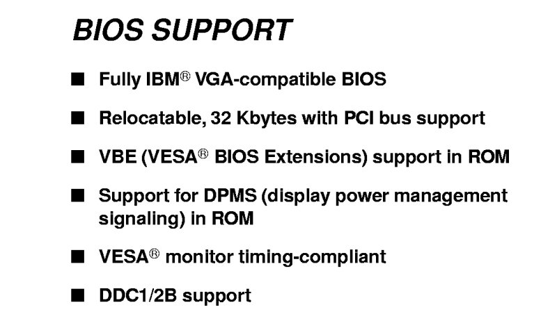
就是说,这亏啊显卡符合 IBM VGA 规范,而这份规范年代久远,资料比较难以找到【参考3】.大概是说显卡的一些基本显示参数(例如:分辨率)是通过IO和显卡沟通的。首先是定义了几个基本的文本显示模式,处于这种文本显示的模式下,直接对下面给出来的内存写入字符和参数(比如颜色,闪烁等等)即可显示出来,这也是很早之前我们使用的DOS 的显示方式。
apping of Display Memory into CPU Address Space
The first element that defines this mapping is whether or not the VGA decodes accesses from the CPU. This is controlled by the RAM Enable field. If display memory decoding is disabled, then the VGA hardware ignores writes to its address space. The address range that the VGA hardware decodes is based upon the Memory Map Select field. The following table shows the address ranges in absolute 32-bit form decoded for each value of this field:
- 00 — A0000h-BFFFFh — 128K
- 01 — A0000h-AFFFFh — 64K
- 10 — B0000h-B7FFFh — 32K
- 11 — B8000h-BFFFFh — 32K
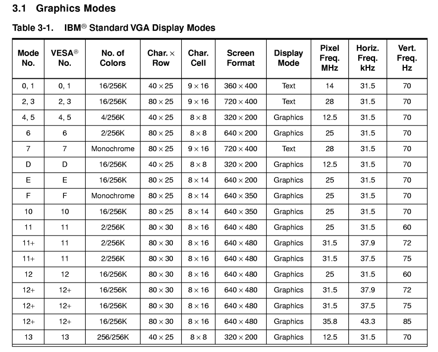
但是,我们的 UEFI 是工作在图形模式下。因此,BIOS需要先通过IO Port (例如:3CEh和3CFh,这些都是 VGA Spec 规定好的端口号)使得显卡切换到图形模式下。例如,下面就是Cirrus CLGD 5446显卡支持的显示模式:
当处于图形模式下之后,就无法通过 B0000 这样的地址写入数据了。同样在 Cirrus CLGD 5446 Data Sheet 上有如下描述,就是说 PCI 空间上会给出显卡内存的地址:
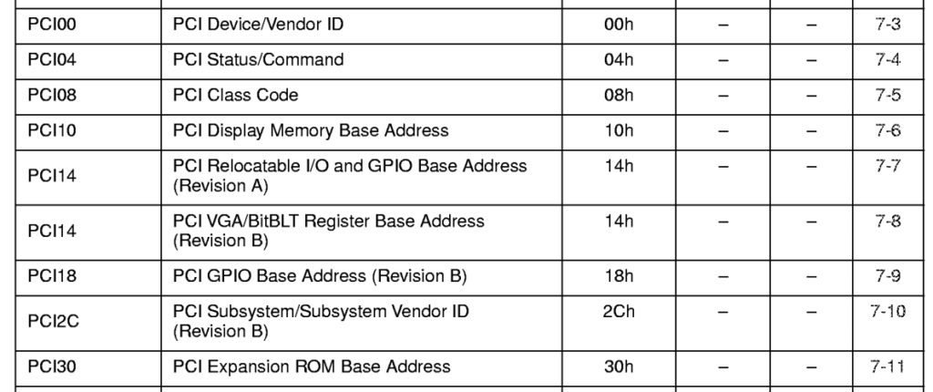
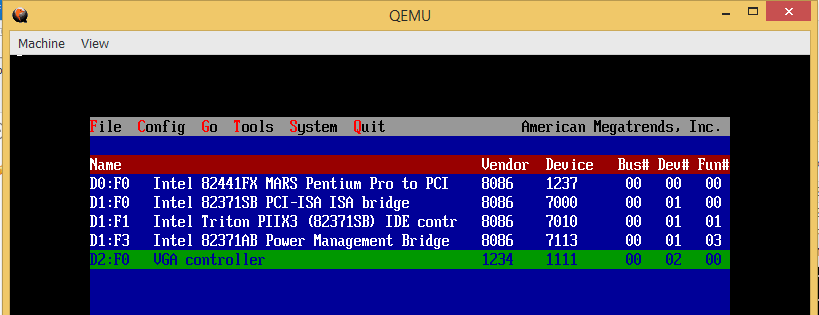
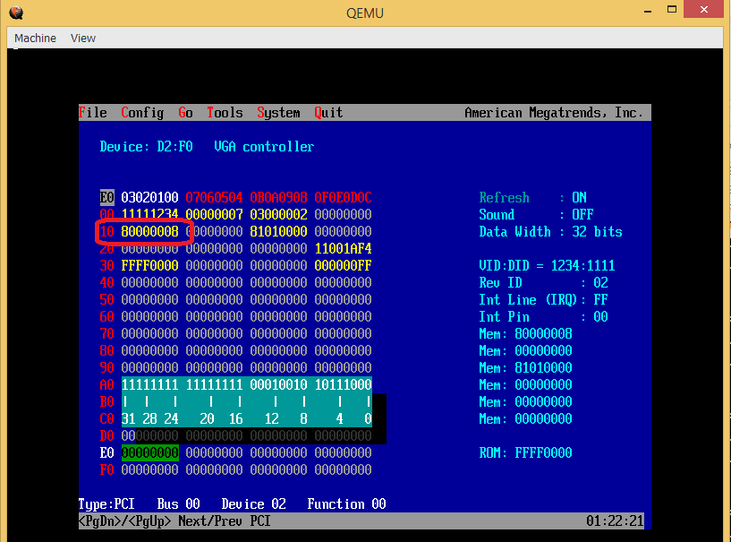
在 QEMU 下用 RU 查看,在VGA PCI 配置空间的配置空间中,可以看到PCI Display Memory Base Address 是 0x8000 0000。
接下来到EDK2代码中查看OVMF 部分的代码:
1.前面提到的通过IO Port 对VGA 进行初始化的操作,在 \OvmfPkg\QemuVideoDxe\Gop.c文件中:
EFI_STATUS
EFIAPI
QemuVideoGraphicsOutputSetMode (
  IN  EFI_GRAPHICS_OUTPUT_PROTOCOL *This,
  IN  UINT32                       ModeNumber
  )
/*++

Routine Description:

  Graphics Output protocol interface to set video mode

  Arguments:
    This             - Protocol instance pointer.
    ModeNumber       - The mode number to be set.

  Returns:
    EFI_SUCCESS      - Graphics mode was changed.
    EFI_DEVICE_ERROR - The device had an error and could not complete the request.
    EFI_UNSUPPORTED  - ModeNumber is not supported by this device.

--*/
2.通过写入 MMIO实现显示的代码,同样在 \OvmfPkg\QemuVideoDxe\Gop.c文件中:
EFI_STATUS
EFIAPI
QemuVideoGraphicsOutputBlt (
  IN  EFI_GRAPHICS_OUTPUT_PROTOCOL          *This,
  IN  EFI_GRAPHICS_OUTPUT_BLT_PIXEL         *BltBuffer, OPTIONAL
  IN  EFI_GRAPHICS_OUTPUT_BLT_OPERATION     BltOperation,
  IN  UINTN                                 SourceX,
  IN  UINTN                                 SourceY,
  IN  UINTN                                 DestinationX,
  IN  UINTN                                 DestinationY,
  IN  UINTN                                 Width,
  IN  UINTN                                 Height,
  IN  UINTN                                 Delta
  )
其中调用了 FrameBufferBlt()
  switch (BltOperation) {
  case EfiBltVideoToBltBuffer:
  case EfiBltBufferToVideo:
  case EfiBltVideoFill:
  case EfiBltVideoToVideo:
    Status = FrameBufferBlt (
      Private->FrameBufferBltConfigure,
      BltBuffer,
      BltOperation,
      SourceX,
      SourceY,
      DestinationX,
      DestinationY,
      Width,
      Height,
      Delta
      );
break;
FrameBufferBlt函数在 \MdeModulePkg\Library\FrameBufferBltLib\FrameBufferBltLib.c文件中:
/**
  Performs a UEFI Graphics Output Protocol Blt operation.

  @param[in]     Configure    Pointer to a configuration which was successfully
                              created by FrameBufferBltConfigure ().
  @param[in,out] BltBuffer    The data to transfer to screen.
  @param[in]     BltOperation The operation to perform.
  @param[in]     SourceX      The X coordinate of the source for BltOperation.
  @param[in]     SourceY      The Y coordinate of the source for BltOperation.
  @param[in]     DestinationX The X coordinate of the destination for
                              BltOperation.
  @param[in]     DestinationY The Y coordinate of the destination for
                              BltOperation.
  @param[in]     Width        The width of a rectangle in the blt rectangle
                              in pixels.
  @param[in]     Height       The height of a rectangle in the blt rectangle
                              in pixels.
  @param[in]     Delta        Not used for EfiBltVideoFill and
                              EfiBltVideoToVideo operation. If a Delta of 0
                              is used, the entire BltBuffer will be operated
                              on. If a subrectangle of the BltBuffer is
                              used, then Delta represents the number of
                              bytes in a row of the BltBuffer.

  @retval RETURN_INVALID_PARAMETER Invalid parameter were passed in.
  @retval RETURN_SUCCESS           The Blt operation was performed successfully.
**/
RETURN_STATUS
EFIAPI
FrameBufferBlt (
  IN     FRAME_BUFFER_CONFIGURE                *Configure,
  IN OUT EFI_GRAPHICS_OUTPUT_BLT_PIXEL         *BltBuffer, OPTIONAL
  IN     EFI_GRAPHICS_OUTPUT_BLT_OPERATION     BltOperation,
  IN     UINTN                                 SourceX,
  IN     UINTN                                 SourceY,
  IN     UINTN                                 DestinationX,
  IN     UINTN                                 DestinationY,
  IN     UINTN                                 Width,
  IN     UINTN                                 Height,
  IN     UINTN                                 Delta
  )
简单起见我们只是研究一下填充函数:
  case EfiBltVideoFill:
    return FrameBufferBltLibVideoFill (
             Configure,
             BltBuffer,
             DestinationX,
             DestinationY,
             Width,
             Height
             );
FrameBufferBltLibVideoFill()函数在\MdeModulePkg\Library\FrameBufferBltLib\FrameBufferBltLib.c代码如下:
/**
  Performs a UEFI Graphics Output Protocol Blt Video Fill.

  @param[in]  Configure     Pointer to a configuration which was successfully
                            created by FrameBufferBltConfigure ().
  @param[in]  Color         Color to fill the region with.
  @param[in]  DestinationX  X location to start fill operation.
  @param[in]  DestinationY  Y location to start fill operation.
  @param[in]  Width         Width (in pixels) to fill.
  @param[in]  Height        Height to fill.

  @retval  RETURN_INVALID_PARAMETER Invalid parameter was passed in.
  @retval  RETURN_SUCCESS           The video was filled successfully.

**/
EFI_STATUS
FrameBufferBltLibVideoFill (
  IN  FRAME_BUFFER_CONFIGURE        *Configure,
  IN  EFI_GRAPHICS_OUTPUT_BLT_PIXEL *Color,
  IN  UINTN                         DestinationX,
  IN  UINTN                         DestinationY,
  IN  UINTN                         Width,
  IN  UINTN                         Height
  )
{}
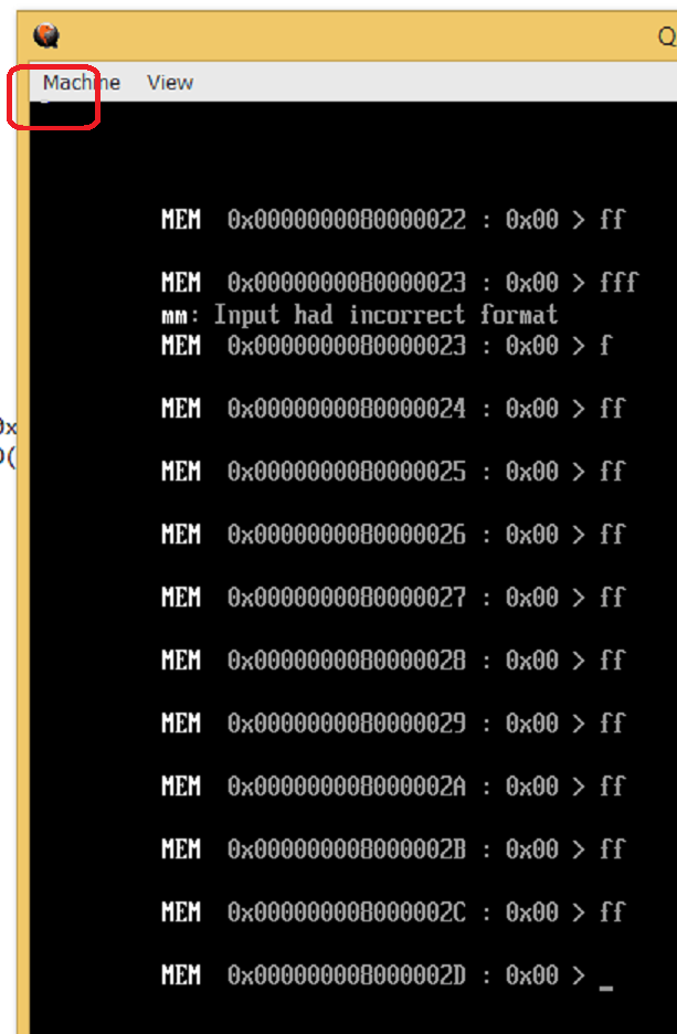
我们可以通过在其中加入DEBUG Message 的方法来判定对显卡的写入操作。经过实验发现,cls 命令之后会在 0x8000 001c 写入0x00。因此,这里实验从这个位置开始写入 0xFF, 可以看到屏幕上出现了一个白色的线条:
总结:UEFI Spec 定义了显卡应该提供什么样的接口给用户调用,但是具体实现由各家自己完成。相比大多数的应该都是简单设定都是 IO 来完成,具体要显示的内容则是通过 MMIO 来完成。
参考: