Windows 11 无网络安装方法

Windows 11 的一些版本默认安装时需要联网登录微软账户,但是大多数测试机不会直接接入互联网,要求联网的要求对于我们的测试造成了极大的不便。这里介绍一下跳过要求联网的方法,有需要的朋友可以尝试本文方法。

1.安装到要求联网的位置,此时会提示当前没有网络

2.使用 shift+F10打开CMD窗口,输入 OOBE\BYPASSNRO, 输入之后会自动重启

3.再次进入之前要求联网的界面会出现 “I don’t have internet”选项,选中这个选项之后就可以继续安装了

4.最后安装成功的界面

Windows 11 内部版本号 25131.1000

Windows 11 22H2下无法运行 RW的解决方法

感谢Tim网友在评论中指出解决 RW_Everyhing 在 Windows 11 22H2 无法运行的方法,正好最近有空于是在虚拟机上研究了一下(顺便说一下,Windows 11 最低系统要求是 4G RAM, 64GB 硬盘, 2 Core CPU,只有按照上述设置才能在虚拟机中跑起来)。

首先安装 22H2 (25131)的 Windows 11,然后确定能够看到现象:

RW_Everything 错误提示
RW_Everything 错误提示

接下来关闭 Core Isolation (直接在搜索中输入 “Core” 字样就会自动跳出来)中的 Microsoft Vulnerable Driver Blocklist:

Core Isolation -> Microsoft Vulnerable Driver Blocklist

然后需要重启一次,就能够启动 Rw_Everything了。

22H2 RW_Everything 工作正常

一些特殊情况无法进行上述的设置还可以更换另外一款类似软件: HE (Hardware Read&Write作者Faintsnow,下载网站 http://hwrwdrv.phpnet.us/?i=1)

=========================================================

2022年7月28日

针对这个问题我咨询了一下我的朋友天杀,他丢给我一个微软的链接:

https://docs.microsoft.com/en-us/windows/security/threat-protection/windows-defender-application-control/microsoft-recommended-driver-block-rules

简单的说,在新版的 Windows 中,微软添加了一个“黑名单”,进入这个名单的 Driver 都会被阻止。这也是为什么很多人发现:之前用的好好的版本忽然之间 RW 无法打开,这是因为 Windows 推送了这个更新,更新之后“黑名单”生效所以之前可以但是现在不行了。

    <FileAttrib ID=”ID_FILEATTRIB_RTKIOW10X64_DRIVER” FriendlyName=”” FileName=”rtkiow10x64.sys” MinimumFileVersion=”65535.65535.65535.65535″ />

    <FileAttrib ID=”ID_FILEATTRIB_RWDRV_DRIVER” FriendlyName=”” FileName=”RwDrv.sys” MinimumFileVersion=”65535.65535.65535.65535″ />

      <FileAttrib ID=”ID_FILEATTRIB_SANDBOX_1″ FriendlyName=”Agnitum sandbox FileAttribute” FileName=”sandbox.sys” MinimumFileVersion=”0.0.0.0″ MaximumFileVersion=”65535.65535.65535.65535″ />

理论上只要对 RW_Everything 的驱动重新签名即可,但是这个意味着如果有一天微软再将新驱动封杀很可能也会影响你的签名本身(用这个签名签发的所有驱动都无法运行)。

目前解决方法:

1.下载这个去除签名版本的 rw 驱动;

RwDrv下载

2.将上述文件放到 windows\system32\driver 目录下

3.管理员权限运行 cmd, 打开 bcdedit /set testsigning on (进入 TestSigning Mode 之后屏幕右下角会有显示)

4.重启之后即可启动 RW_Everyting

5.只要不 disable TestSigning Mode,就可以一直使用 RW_Everything

6.关闭 TestSigning 的方法是: bcdedit /set testsigning off

========================================================

2022年8月10日 更新

一位匿名网友的建议可以通过修改注册表达到让 RW 工作的目标:

Windows Registry Editor Version 5.00

[HKEY_LOCAL_MACHINE\SYSTEM\CurrentControlSet\Control\CI\Config]
“VulnerableDriverBlocklistEnable”=dword:00000000

经过测试这个方法可行,这里表示感谢!

Step to UEFI (255)PlatformPei之后

当BIOS执行完 PlatformPei.efi 之后,不会和其他PeiM 一样继续执行而是要进行一些特别的处理。

在\MdeModulePkg\Core\Pei\Dispatcher\Dispatcher.c 文件 PeiDispatcher函数中会 invoke 每一个PEIM。

/**
  Conduct PEIM dispatch.

  @param SecCoreData     Points to a data structure containing information about the PEI core's operating
                         environment, such as the size and location of temporary RAM, the stack location and
                         the BFV location.
  @param Private         Pointer to the private data passed in from caller

**/
VOID
PeiDispatcher (
  IN CONST EFI_SEC_PEI_HAND_OFF  *SecCoreData,
  IN PEI_CORE_INSTANCE           *Private
  )

这里会调用每个 PEIM 的 EntryPoint, 有兴趣的朋友可以在此加入 Debug Message.

                  //
                  // Call the PEIM entry point for PEIM driver
                  //
                  PeimEntryPoint = (EFI_PEIM_ENTRY_POINT2)(UINTN)EntryPoint;
                  PeimEntryPoint (PeimFileHandle, (const EFI_PEI_SERVICES **) PeiServices);
                  Private->PeimDispatchOnThisPass = TRUE;

特别提一句,在\mdemodulepkg\core\pei\dispatcher\Dispatcher.c这个文件中,大多数 DEBUG message是通过下面的方式输出的:

DEBUG ((DEBUG_DISPATCH, "Evaluate PEI DEPEX for FFS(Unknown)\n"));

但是如果你也用这种方式,会发现无法在Log 文件中看到消息的。这是因为在\OvmfPkg\OvmfPkgX64.dsc 中定义如下:

  # DEBUG_INIT      0x00000001  // Initialization
  # DEBUG_WARN      0x00000002  // Warnings
  # DEBUG_LOAD      0x00000004  // Load events
  # DEBUG_FS        0x00000008  // EFI File system
  # DEBUG_POOL      0x00000010  // Alloc &amp; Free (pool)
  # DEBUG_PAGE      0x00000020  // Alloc &amp; Free (page)
  # DEBUG_INFO      0x00000040  // Informational debug messages
  # DEBUG_DISPATCH  0x00000080  // PEI/DXE/SMM Dispatchers
  # DEBUG_VARIABLE  0x00000100  // Variable
  # DEBUG_BM        0x00000400  // Boot Manager
  # DEBUG_BLKIO     0x00001000  // BlkIo Driver
  # DEBUG_NET       0x00004000  // SNP Driver
  # DEBUG_UNDI      0x00010000  // UNDI Driver
  # DEBUG_LOADFILE  0x00020000  // LoadFile
  # DEBUG_EVENT     0x00080000  // Event messages
  # DEBUG_GCD       0x00100000  // Global Coherency Database changes
  # DEBUG_CACHE     0x00200000  // Memory range cachability changes
  # DEBUG_VERBOSE   0x00400000  // Detailed debug messages that may
  #                             // significantly impact boot performance
  # DEBUG_ERROR     0x80000000  // Error
gEfiMdePkgTokenSpaceGuid.PcdDebugPrintErrorLevel|0x8000004F

默认是没有DEBUG_DISPATCH  的,所以要么将 PcdDebugPrintErrorLevel 设置为0x800000CF,要么在 DEBUG 宏中使用DEBUG_INFO参数。

从PlatformPei.efi出来之后,因为内存初始化已完成,进入下面的函数之后 PeiCheckAndSwitchStack (SecCoreData, Private);会检查

Private->SwitchStackSignal是否已经Enable。 具体的是在\mdemodulepkg\core\pei\memory\MemoryServices.c 代码中设置起来的。

/**

  This function registers the found memory configuration with the PEI Foundation.

  The usage model is that the PEIM that discovers the permanent memory shall invoke this service.
  This routine will hold discoveried memory information into PeiCore's private data,
  and set SwitchStackSignal flag. After PEIM who discovery memory is dispatched,
  PeiDispatcher will migrate temporary memory to permanent memory.

  @param PeiServices        An indirect pointer to the EFI_PEI_SERVICES table published by the PEI Foundation.
  @param MemoryBegin        Start of memory address.
  @param MemoryLength       Length of memory.

  @return EFI_SUCCESS Always success.

**/
EFI_STATUS
EFIAPI
PeiInstallPeiMemory (
  IN CONST EFI_PEI_SERVICES  **PeiServices,
  IN EFI_PHYSICAL_ADDRESS    MemoryBegin,
  IN UINT64                  MemoryLength
  )

一句话:当BIOS执行完 PlatformPei.efi 之后内存可用。

Temp Stack : BaseAddress=0x818000 Length=0x8000
Temp Heap  : BaseAddress=0x810000 Length=0x8000
Total temporary memory:    65536 bytes.
  temporary memory stack ever used:       29192 bytes.
  temporary memory heap used for HobList: 6608 bytes.
  temporary memory heap occupied by memory pages: 0 bytes.
Memory Allocation 0x0000000A 0x7F78000 - 0x7FFFFFF
Memory Allocation 0x0000000A 0x810000 - 0x81FFFF
Memory Allocation 0x0000000A 0x807000 - 0x807FFF
Memory Allocation 0x0000000A 0x800000 - 0x805FFF
Memory Allocation 0x0000000A 0x806000 - 0x806FFF
Memory Allocation 0x00000006 0x7EF4000 - 0x7F77FFF
Memory Allocation 0x0000000A 0x820000 - 0x8FFFFF
Memory Allocation 0x00000004 0x900000 - 0x14FFFFF
Old Stack size 32768, New stack size 131072
Stack Hob: BaseAddress=0x3F36000 Length=0x20000
Heap Offset = 0x3746000 Stack Offset = 0x3736000
TemporaryRamMigration(0x810000, 0x3F4E000, 0x10000)

在运行PeiCheckAndSwitchStack() 函数的过程中输出上述Log。之后,再次跳入 PeiCore 进行执行,此时内存已经 Ready。

      //
      // Entry PEI Phase 2
      //
      PeiCore (SecCoreData, NULL, Private);

我们能够看到的Log 如下:

Loading PEIM 52C05B14-0B98-496C-BC3B-04B50211D680
Loading PEIM at 0x00007EE7000 EntryPoint=0x00007EE7538 PeiCore.efi
Reinstall PPI: 8C8CE578-8A3D-4F1C-9935-896185C32DD3
Reinstall PPI: 5473C07A-3DCB-4DCA-BD6F-1E9689E7349A
Reinstall PPI: B9E0ABFE-5979-4914-977F-6DEE78C278A6
Install PPI: F894643D-C449-42D1-8EA8-85BDD8C65BDE
Loading PEIM 9B3ADA4F-AE56-4C24-8DEA-F03B7558AE50
Loading PEIM at 0x00007EE1000 EntryPoint=0x00007EE14C8 PcdPeim.efi
Reinstall PPI: 06E81C58-4AD7-44BC-8390-F10265F72480
Reinstall PPI: 4D8B155B-C059-4C8F-8926-06FD4331DB8A
Reinstall PPI: 01F34D25-4DE2-23AD-3FF3-36353FF323F1
Reinstall PPI: A60C6B59-E459-425D-9C69-0BCC9CB27D81

就是说再次进入 Peicore 之后重新执行了 PcdPeim.efi。

Step to UEFI (254)PlatformPei 分析

继续跟着Log 分析,加载了PlatformPei.efi,它代码位于 \OvmfPkg\PlatformPei 目录中。

Loading PEIM 222C386D-5ABC-4FB4-B124-FBB82488ACF4
Loading PEIM at 0x00000851920 EntryPoint=0x00000851F70 PlatformPei.efi

从Log 中可以看到,刚进入这个 Module 之后,调用到位于\OvmfPkg\Library\QemuFwCfgLib\QemuFwCfgPei.c 的QemuFwCfgInitialize() 函数中。QemuFwCfgPeiLib.inf 中指定了这个函数作为这个 PEIM 的构造函数。

  CONSTRUCTOR                    = QemuFwCfgInitialize

接下来的 Log 是:

Select Item: 0x0
FW CFG Signature: 0x554D4551
Select Item: 0x1
FW CFG Revision: 0x3
QemuFwCfg interface (DMA) is supported.

对应 \OvmfPkg\PlatformPei\Platform.c 中的如下函数:

/**
  Perform Platform PEI initialization.

  @param  FileHandle      Handle of the file being invoked.
  @param  PeiServices     Describes the list of possible PEI Services.

  @return EFI_SUCCESS     The PEIM initialized successfully.

**/
EFI_STATUS
EFIAPI
InitializePlatform (
  IN       EFI_PEI_FILE_HANDLE  FileHandle,
  IN CONST EFI_PEI_SERVICES     **PeiServices
  )
Platform PEIM Loaded
CMOS:
00: 44 00 54 00 06 00 02 13 12 21 26 02 10 80 00 00
10: 50 00 00 00 07 80 02 FF FF 00 00 00 00 00 00 00
20: 00 00 00 00 00 00 00 00 00 00 00 00 00 00 00 00
30: FF FF 20 00 00 07 00 20 30 00 00 00 00 12 00 00
40: 00 00 00 00 00 00 00 00 00 00 00 00 00 00 00 00
50: 00 00 00 00 00 00 00 00 00 00 00 00 00 00 00 00
60: 00 00 00 00 00 00 00 00 00 00 00 00 00 00 00 00
70: 00 00 00 00 00 00 00 00 00 00 00 00 00 00 00 00

这里会调用到\OvmfPkg\Library\QemuFwCfgS3Lib\QemuFwCfgS3PeiDxe.c中的QemuFwCfgS3Enabled()

/**
  Determine if S3 support is explicitly enabled.

  @retval  TRUE   If S3 support is explicitly enabled. Other functions in this
                  library may be called (subject to their individual
                  restrictions).

           FALSE  Otherwise. This includes unavailability of the firmware
                  configuration interface. No other function in this library
                  must be called.
**/
BOOLEAN
EFIAPI
QemuFwCfgS3Enabled (
  VOID
  ) 

QEMU 模拟了 SPI ROM,使得BIOS能够访问到一些设置。

Select Item: 0x19
Select Item: 0x27
S3 support was detected on QEMU
  if (QemuFwCfgS3Enabled ()) {
    DEBUG ((DEBUG_INFO, "S3 support was detected on QEMU\n"));
    mS3Supported = TRUE;
    Status = PcdSetBoolS (PcdAcpiS3Enable, TRUE);
    ASSERT_EFI_ERROR (Status);
  }
Install PPI: 7408D748-FC8C-4EE6-9288-C4BEC092A410

BootModeInitialization() 中的Status = PeiServicesInstallPpi (mPpiBootMode); 输出

Select Item: 0x19
Select Item: 0x25
ScanOrAdd64BitE820Ram: Base=0x0 Length=0x8000000 Type=1
Select Item: 0x19
Select Item: 0x19
GetFirstNonAddress: Pci64Base=0x800000000 Pci64Size=0x800000000
Select Item: 0x5

对应代码在 \ovmfpkg\platformpei\MemDetect.c

/**
  Iterate over the RAM entries in QEMU's fw_cfg E820 RAM map that start outside
  of the 32-bit address range.

  Find the highest exclusive >=4GB RAM address, or produce memory resource
  descriptor HOBs for RAM entries that start at or above 4GB.

  @param[out] MaxAddress  If MaxAddress is NULL, then ScanOrAdd64BitE820Ram()
                          produces memory resource descriptor HOBs for RAM
                          entries that start at or above 4GB.

                          Otherwise, MaxAddress holds the highest exclusive
                          >=4GB RAM address on output. If QEMU's fw_cfg E820
                          RAM map contains no RAM entry that starts outside of
                          the 32-bit address range, then MaxAddress is exactly
                          4GB on output.

  @retval EFI_SUCCESS         The fw_cfg E820 RAM map was found and processed.

  @retval EFI_PROTOCOL_ERROR  The RAM map was found, but its size wasn't a
                              whole multiple of sizeof(EFI_E820_ENTRY64). No
                              RAM entry was processed.

  @return                     Error codes from QemuFwCfgFindFile(). No RAM
                              entry was processed.
**/
STATIC
EFI_STATUS
ScanOrAdd64BitE820Ram (
  OUT UINT64 *MaxAddress OPTIONAL
  )
MaxCpuCountInitialization: CmdData2=0x0
MaxCpuCountInitialization: QEMU v2.7 reset bug: BootCpuCount=1 Present=0
MaxCpuCountInitialization: BootCpuCount=0 mMaxCpuCount=1

PublishPeiMemory: mPhysMemAddressWidth=36 PeiMemoryCap=65800 KB
PeiInstallPeiMemory MemoryBegin 0x3F36000, MemoryLength 0x4042000

QEMU 的内存初始化在  \ovmfpkg\platformpei\MemDetect.c

/**
  Publish PEI core memory

  @return EFI_SUCCESS     The PEIM initialized successfully.

**/
EFI_STATUS
PublishPeiMemory (
  VOID
  )
  PublishPeiMemory ();

QemuUc32BaseInitialization: rounded UC32 base from 0x8000000 up to 0x80000000, for an UC32 size of 0x80000000

VOID
QemuUc32BaseInitialization (
  VOID
  )
QemuInitializeRam called

具体实现在 \ovmfpkg\platformpei\MemDetect.c 文件中

/**
  Publish system RAM and reserve memory regions

**/
VOID
InitializeRamRegions (
  VOID
  )
QemuInitializeRam ();
/**
  Peform Memory Detection for QEMU / KVM

**/
STATIC
VOID
QemuInitializeRam (
  VOID
  )
Platform PEI Firmware Volume Initialization
Install PPI: 49EDB1C1-BF21-4761-BB12-EB0031AABB39
Notify: PPI Guid: 49EDB1C1-BF21-4761-BB12-EB0031AABB39, Peim notify entry point: 82153C
The 1th FV start address is 0x00000900000, size is 0x00C00000, handle is 0x900000
Select Item: 0x19
Register PPI Notify: EE16160A-E8BE-47A6-820A-C6900DB0250A
Select Item: 0x19
\MdePkg\MdePkg.dec
  ## Include/Ppi/MpServices.h
  gEfiPeiMpServicesPpiGuid           = { 0xee16160a, 0xe8be, 0x47a6, { 0x82, 0xa, 0xc6, 0x90, 0xd, 0xb0, 0x25, 0xa } }

PlatformPei.efi 中有大量和“硬件”相关的内容,最重要的部分是内存的初始化,运行完成后,内存可用。

参考:

1. https://www.lab-z.com/stu238/ OVMF 从第一条指令到 SecMain

英文版 Windows Python 窗口显示汉字

这次介绍一下如何在英文版 Windows的 CMD 窗口中显示中文的方法。例如,有如下代码,保存在 test.py 中:

print ("Hello,world!")
print (u"学习")

直接运行显示如下:

这时候我们使用命令置活动代码页编号:

再进行测试即可显示:

同样的,我们可以直接在修改代码自动切换:

import os
os.system('chcp 936')
print ("Hello,world!")
print (u"学习")

Step to UEFI (253)PEIM 调用顺序研究

当EFI 刚出现的时候,模块没有固定的加载顺序是作为优点介绍的,但是运行过程确实需要加载顺序,这一切是通过源代码中每个模块 INF 中[Depex] Section 决定的。前面的文章中提到了PEIM 加载了一些模块,根据 Log 输出的信息对其运行顺序进行排序结果如下:

顺序文件名INF 文件位置Depex
1PcdPeim.efi\MdeModulePkg\Universal\PCD\Pei\Pcd.infTRUE
2ReportStatusCodeRouterPei.efi\MdeModulePkg\Universal\ReportStatusCodeRouter\Pei\ReportStatusCodeRouterPei.infTRUE
3StatusCodeHandlePei.efi\MdeModulePkg\Universal\StatusCodeHandler\Pei\StatusCodeHandlerPei.infTRUE
4PlatformPei.efi\OvmfPkg\PlatformPei\PlatformPei.infTRUE
 (PeiCore.efi) N/A*
5PcdPeim.efi\MdeModulePkg\Universal\PCD\Pei\Pcd.infTRUE
6DxeIpl.efi\MdeModulePkg\Core\DxeIplPeim\DxeIpl.infgEfiPeiLoadFilePpiGuid AND gEfiPeiMasterBootModePpiGuid
7S3Resume2Pei.efi\UefiCpuPkg\Universal\Acpi\S3Resume2Pei\S3Resume2Pei.infTRUE
8CpuMpPei.efi\UefiCpuPkg\CpuMpPei\CpuMpPei.infTRUE
9DxeCore.efi这里已经进入 DXE 了N/A*
*PeiCore和DxeCore 不是 PEIM 所以没有 Depex。

(有兴趣的朋友可以按照上面给出的 INF 文件中的 ENTRY_POINT 处添加 DEBUG)

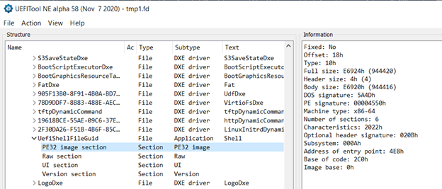
可以看到,上述的 PEIM 中大部分 DEPEX 都是 TRUE 就是不依赖任何条件。对于这种,猜测是根据压缩打包的前后顺序来决定,前面使用过 UEFITool NE 检查过生成的文件,可以看到大致顺序:

接下来来研究如何改变这个顺序。在 \OvmfPkg\OvmfPkgX64.fdf 文件中有如下代码:

#
#  PEI Phase modules
#
INF  MdeModulePkg/Core/Pei/PeiMain.inf
INF  MdeModulePkg/Universal/PCD/Pei/Pcd.inf
INF  MdeModulePkg/Universal/ReportStatusCodeRouter/Pei/ReportStatusCodeRouterPei.inf
INF  MdeModulePkg/Universal/StatusCodeHandler/Pei/StatusCodeHandlerPei.inf
INF  OvmfPkg/PlatformPei/PlatformPei.inf
INF  MdeModulePkg/Core/DxeIplPeim/DxeIpl.inf
INF  UefiCpuPkg/Universal/Acpi/S3Resume2Pei/S3Resume2Pei.inf
!if $(SMM_REQUIRE) == TRUE
INF  MdeModulePkg/Universal/FaultTolerantWritePei/FaultTolerantWritePei.inf
INF  MdeModulePkg/Universal/Variable/Pei/VariablePei.inf
INF  OvmfPkg/SmmAccess/SmmAccessPei.inf
!endif
INF  UefiCpuPkg/CpuMpPei/CpuMpPei.inf

我们进行一下修改,将 CpuMpPei.inf 放在最前面。

#
#  PEI Phase modules
#
INF  UefiCpuPkg/CpuMpPei/CpuMpPei.inf
INF  MdeModulePkg/Core/Pei/PeiMain.inf
NF  MdeModulePkg/Universal/PCD/Pei/Pcd.inf
INF  MdeModulePkg/Universal/ReportStatusCodeRouter/Pei/ReportStatusCodeRouterPei.inf
INF  MdeModulePkg/Universal/StatusCodeHandler/Pei/StatusCodeHandlerPei.inf
INF  OvmfPkg/PlatformPei/PlatformPei.inf
INF  MdeModulePkg/Core/DxeIplPeim/DxeIpl.inf
INF  UefiCpuPkg/Universal/Acpi/S3Resume2Pei/S3Resume2Pei.inf
!if $(SMM_REQUIRE) == TRUE
INF  MdeModulePkg/Universal/FaultTolerantWritePei/FaultTolerantWritePei.inf
INF  MdeModulePkg/Universal/Variable/Pei/VariablePei.inf
INF  OvmfPkg/SmmAccess/SmmAccessPei.inf
!endif

这样修改之后再次使用工具查看,可以看到 CpuMpPei确实排在第一位:

但是从 Log 上来看CpuMpPei加载位置提前了,但是加载的第一个 PEIM 仍然是 PcdPeim:

The 0th FV start address is 0x00000820000, size is 0x000E0000, handle is 0x820000
Register PPI Notify: 49EDB1C1-BF21-4761-BB12-EB0031AABB39
Register PPI Notify: EA7CA24B-DED5-4DAD-A389-BF827E8F9B38
Install PPI: B9E0ABFE-5979-4914-977F-6DEE78C278A6
Install PPI: DBE23AA9-A345-4B97-85B6-B226F1617389
DiscoverPeimsAndOrderWithApriori(): Found 0x7 PEI FFS files in the 0th FV
Loading PEIM 9B3ADA4F-AE56-4C24-8DEA-F03B7558AE50
Loading PEIM at 0x0000083A7A0 EntryPoint=0x0000083AC68 PcdPeim.efi
Install PPI: 06E81C58-4AD7-44BC-8390-F10265F72480
Install PPI: 01F34D25-4DE2-23AD-3FF3-36353FF323F1
Install PPI: 4D8B155B-C059-4C8F-8926-06FD4331DB8A
Install PPI: A60C6B59-E459-425D-9C69-0BCC9CB27D81
Register PPI Notify: 605EA650-C65C-42E1-BA80-91A52AB618C6
Loading PEIM EDADEB9D-DDBA-48BD-9D22-C1C169C8C5C6
Loading PEIM at 0x00000820120 EntryPoint=0x00000821364 CpuMpPei.efi
Register PPI Notify: F894643D-C449-42D1-8EA8-85BDD8C65BDE
Loading PEIM A3610442-E69F-4DF3-82CA-2360C4031A23
Loading PEIM at 0x00000840220 EntryPoint=0x000008406E8 ReportStatusCodeRouterPei.efi
Install PPI: 0065D394-9951-4144-82A3-0AFC8579C251
Install PPI: 229832D3-7A30-4B36-B827-F40CB7D45436
Loading PEIM 9D225237-FA01-464C-A949-BAABC02D31D0
Loading PEIM at 0x00000842D20 EntryPoint=0x000008431A8 StatusCodeHandlerPei.efi

进一步研究,在【参考1】有提到:

“在PEIM Dispatcher寻找可启动的PEIM时,会先在每一个FV上定位Apriori文件,然后读取文件内容来查找PEIM的GUID,确保Apriori文件中的PEIM被首先调用。在OvmfPkgX64.fdf中我们可以看到FV.PEIFV中有以下内容:

APRIORI PEI {

INF  MdeModulePkg/Universal/PCD/Pei/Pcd.inf

}“

就是说 PeiDispatcher() 函数会先分析 Apriori 文件,然后首先执行其中指定的PEIM,对应的 OvmfPkgX64.fdf 中指定了 PcdPeim.efi,所以这个文件会首先被执行到。

      if (Private->CurrentPeimCount == 0) {
        //
        // When going through each FV, at first, search Apriori file to
        // reorder all PEIMs to ensure the PEIMs in Apriori file to get
        // dispatch at first.
        //
        DiscoverPeimsAndOrderWithApriori (Private, CoreFvHandle);
      }

接下来编写一个最简单的 PEI Driver, 其中只有输出信息的动作:

  DEBUG ((DEBUG_INFO, "LABZ Test PEIM\n"));

修改如下2个文件加入OVMF 的编译:

1.OvmfPkgX64.dsc

!if $(SMM_REQUIRE) == TRUE
      LockBoxLib|MdeModulePkg/Library/SmmLockBoxLib/SmmLockBoxPeiLib.inf
!endif
  }
  
  OvmfPkg/TestPei/TestPei.inf
  
!if $(SMM_REQUIRE) == TRUE
  MdeModulePkg/Universal/FaultTolerantWritePei/FaultTolerantWritePei.inf
  MdeModulePkg/Universal/Variable/Pei/VariablePei.inf
  OvmfPkg/SmmAccess/SmmAccessPei.inf
!endif

2.OvmfPkgX64.fdf

INF  MdeModulePkg/Core/DxeIplPeim/DxeIpl.inf
INF  UefiCpuPkg/Universal/Acpi/S3Resume2Pei/S3Resume2Pei.inf
!if $(SMM_REQUIRE) == TRUE
INF  MdeModulePkg/Universal/FaultTolerantWritePei/FaultTolerantWritePei.inf
INF  MdeModulePkg/Universal/Variable/Pei/VariablePei.inf
INF  OvmfPkg/SmmAccess/SmmAccessPei.inf
!endif
INF  OvmfPkg/TestPei/TestPei.inf

!if $(TPM_ENABLE) == TRUE
INF  OvmfPkg/Tcg/TpmMmioSevDecryptPei/TpmMmioSevDecryptPei.inf
INF  OvmfPkg/Tcg/Tcg2Config/Tcg2ConfigPei.inf
INF  SecurityPkg/Tcg/TcgPei/TcgPei.inf
INF  SecurityPkg/Tcg/Tcg2Pei/Tcg2Pei.inf
!endif

运行结果如下:

Loading PEIM 89E549B0-7CFE-449D-9BA3-10D8B2312D71
Loading PEIM at 0x00007ECD000 EntryPoint=0x00007ECD5C8 S3Resume2Pei.efi
Install PPI: 6D582DBC-DB85-4514-8FCC-5ADF6227B147
Loading PEIM 122C386D-5ABC-4FB4-B124-FBB82488ACF4
Loading PEIM at 0x00007ECA000 EntryPoint=0x00007ECA470 TestPei.efi
DiscoverPeimsAndOrderWithApriori(): Found 0x0 PEI FFS files in the 1th FV
DXE IPL Entry
Loading PEIM D6A2CB7F-6A18-4E2F-B43B-9920A733700A
Loading PEIM at 0x00007EA3000 EntryPoint=0x00007EA3D78 DxeCore.efi
Loading DXE CORE at 0x00007EA3000 EntryPoint=0x00007EA3D78

之后,尝试将这个PEIM放在APRIORI 中最前面:

APRIORI PEI {
  INF  OvmfPkg/TestPei/TestPei.inf
  INF  MdeModulePkg/Universal/PCD/Pei/Pcd.inf
}

运行结果如下:

The 0th FV start address is 0x00000820000, size is 0x000E0000, handle is 0x820000
Register PPI Notify: 49EDB1C1-BF21-4761-BB12-EB0031AABB39
Register PPI Notify: EA7CA24B-DED5-4DAD-A389-BF827E8F9B38
Install PPI: B9E0ABFE-5979-4914-977F-6DEE78C278A6
Install PPI: DBE23AA9-A345-4B97-85B6-B226F1617389
DiscoverPeimsAndOrderWithApriori(): Found 0x8 PEI FFS files in the 0th FV
Loading PEIM 122C386D-5ABC-4FB4-B124-FBB82488ACF4
Loading PEIM at 0x0000085A820 EntryPoint=0x0000085AC90 TestPei.efi
Loading PEIM 9B3ADA4F-AE56-4C24-8DEA-F03B7558AE50
Loading PEIM at 0x0000083A7A0 EntryPoint=0x0000083AC68 PcdPeim.efi
Install PPI: 06E81C58-4AD7-44BC-8390-F10265F72480
Install PPI: 01F34D25-4DE2-23AD-3FF3-36353FF323F1
Install PPI: 4D8B155B-C059-4C8F-8926-06FD4331DB8A
Install PPI: A60C6B59-E459-425D-9C69-0BCC9CB27D81
Register PPI Notify: 605EA650-C65C-42E1-BA80-91A52AB618C6

可以看到 TestPei 先于PcdPeim运行。

总结:

  1. fdf 文件中 APRIORI PEI  指定的优先级最高;
  2. 模块中 INF 文件 Depex Section 可以指定依赖关系;
  3. 同等优先级的由fdf中的先后顺序决定。

特别强调上述只是为了实验学习之用,在实际工作中请勿轻易调整 PEIM 顺序避免导致奇怪的问题。另外,对于PEIM 调用顺序还可以参考 PI Spec 中 “PEI Dispatcher Introduction”章节描述。

本文使用的自己编写的 PEIM 如下:

参考:

1. https://blog.csdn.net/weixin_39945816/article/details/111506524 uefi下的开机顺序_UEFI启动过程与协议加载顺序

ESP32 S2 上实现假U盘(ESP32 2.0.1 )

这次介绍的是在 Arduino 1.8.16 + ESP32 2.0.1 下实现假U盘的例子。特别强调:ESP32 Arduino 环境必须是 2.0.1, 更高的版本反倒有兼容问题。

实现的方法和之前的相同【参考1】:

  1. 首先在本机做一个虚拟的256MB硬盘,然后在上面放置一个 200MB 的内容为全0x00的文件(太大的话,处理起来非常麻烦);
  2. 将这个硬盘使用HXD 做成镜像文件,然后使用工具扫描这个文件,将所有的不为0的内容写入.h文件中(这就是256MBDisk.bin.h文件的来源);
  3. 这个文件中0x804 到 0x8CC扇区内容,和0x902 到 0x9CA扇区内容相同,因此在数组中删除后者内容,当有到这个扇区的请求时,用前者的内容替代,这样可以大大缩减编译后文件的体积;
  4. 在代码中响应 onRead(),如果请求的LBA在.h文件中,就进行Buffer 的填充;
  5. 插入过程 Windows 有写入操作,因此必须响应 onWrite

完整代码如下:

#include "USB.h"
#include "USBMSC.h"
#include "256MBDisk.h"

#if ARDUINO_USB_CDC_ON_BOOT
#define HWSerial Serial0
#define USBSerial Serial
#else
#define HWSerial Serial
//USBCDC USBSerial;
#endif

USBMSC MSC;

uint32_t findLBA(uint32_t LBA) {
  for (uint32_t i=0; i<415;i++) {
      if (Index[i]==LBA) {
          if (i>=205) {i=i-205+4;}
          return i;
        }
    }
  return 0xFFFFFF;  
}
static const uint32_t DISK_SECTOR_COUNT = 520192; 

static int32_t onRead(uint32_t lba, uint32_t offset, void* buffer, uint32_t bufsize){
  //HWSerial.printf("MSC READ: lba: %u, offset: %u, bufsize: %u\n", lba, offset, bufsize);

  uint32_t getLBA=0;
  uint8_t *p;
  p=(uint8_t *)buffer;
  //HWSerial.printf("Buffer1 %X\n", buffer);
  for (uint32_t i=0;i<bufsize/DISK_SECTOR_SIZE;i++) {
     //HWSerial.printf("Check %u\n", lba+i);
     getLBA=findLBA(lba+i);
     //HWSerial.printf("getLBA %u %u\n", getLBA,lba+i);
     if (getLBA!=0xFFFFFF) { //如果找到了
        memcpy((void *)&p[i*DISK_SECTOR_SIZE], &msc_disk[getLBA][0], DISK_SECTOR_SIZE);
        //HWSerial.printf("%u %u %u %u\n", msc_disk[getLBA][0],msc_disk[getLBA][1],msc_disk[getLBA][2],msc_disk[getLBA][3]);
        //HWSerial.printf("Send %u\n", getLBA);
        //HWSerial.printf("Buffer2 %X\n", (void *)&p[i*DISK_SECTOR_SIZE]);
      } else {
       //HWSerial.printf("Send all zero to %u\n", getLBA);
        for (uint16_t j=0;j<DISK_SECTOR_SIZE;j++) {
              p[i*DISK_SECTOR_SIZE+j]=0;
          }
          
      }
    }
  return bufsize;
}

static bool onStartStop(uint8_t power_condition, bool start, bool load_eject){
  HWSerial.printf("MSC START/STOP: power: %u, start: %u, eject: %u\n", power_condition, start, load_eject);
  return true;
}

static void usbEventCallback(void* arg, esp_event_base_t event_base, int32_t event_id, void* event_data){
  if(event_base == ARDUINO_USB_EVENTS){
    arduino_usb_event_data_t * data = (arduino_usb_event_data_t*)event_data;
    switch (event_id){
      case ARDUINO_USB_STARTED_EVENT:
        HWSerial.println("USB PLUGGED");
        break;
      case ARDUINO_USB_STOPPED_EVENT:
        HWSerial.println("USB UNPLUGGED");
        break;
      case ARDUINO_USB_SUSPEND_EVENT:
        HWSerial.printf("USB SUSPENDED: remote_wakeup_en: %u\n", data->suspend.remote_wakeup_en);
        break;
      case ARDUINO_USB_RESUME_EVENT:
        HWSerial.println("USB RESUMED");
        break;
      
      default:
        break;
    }
  }
}

static int32_t onWrite(uint32_t lba, uint32_t offset, uint8_t* buffer, uint32_t bufsize){
  HWSerial.printf("MSC WRITE: lba: %u, offset: %u, bufsize: %u\n", lba, offset, bufsize);
  return bufsize;
}
void setup() {
  HWSerial.begin(115200);
  HWSerial.setDebugOutput(true);

  USB.onEvent(usbEventCallback);
  MSC.vendorID("ESP32");//max 8 chars
  MSC.productID("USB_MSC");//max 16 chars
  MSC.productRevision("1.02");//max 4 chars
  MSC.onStartStop(onStartStop);
  MSC.onRead(onRead);
  MSC.onWrite(onWrite);
  MSC.mediaPresent(true);
  MSC.begin(DISK_SECTOR_COUNT, DISK_SECTOR_SIZE);
  //USBSerial.begin();
  USB.begin();
}

void loop() {
  // put your main code here, to run repeatedly:
}

速度测试:

本文提到的用于测试的 U盘镜像:

代码1,这个是完整的分区:

代码2,这个是压缩后的分区(分区的FAT 表有部分是相同的,所以可以对这部分进行压缩)

参考:

  1. https://mc.dfrobot.com.cn/thread-309859-1-1.html ESP32 S2 做一个假U盘

Intel GOP 简介

GOP是 Grapshics Output Protocol 的缩写,这是 UEFI 定义的 Pre-OS 显示接口,目标就是提供显示的基本功能。 无论你使用何种显卡,如果想让屏幕在开机过程有所显示,必须遵从这个协议。这次简单介绍一下 Intel 的 GOP。

Intel 的GOP 会放在BIOS 中,可以看作 BIOS 的一部分。Intel Release 的 GOP有三部分:

1.IntelGopDriver: 这是DXE 的GOP Driver

2.IntelGraphicsPeim: 这是 PEI 阶段的 GOP。用户按下开机键后会希望尽快点亮屏幕看到提示信息,因此在 PEI 阶段点亮屏幕是非常必要的。如果希望上电就能显示,还可以去找屏幕厂商进行定制。

3.VBT:GOP 的配置文件,比如:要求某个端口输出eDP 还是HDMI信号。

BIOS 会在 PEI 阶段 调用IntelGraphicsPeim,然后 DXE 阶段调用IntelGopDriver.efi。和其他的 UEFI 下的Driver一样,这两个文件是C语言编写的,如果由需要可以联系Intel FAE 索要 DEBUG 版本的 GOP。

在OS启动过程中,OS Loader会通过 ExitBootervices()通知 Driver 退出,这时 GOP 会在从系统中卸载。但是 Intel GFX Driver会继续使用 VBT 提供的配置信息(之前的文章提到过如何在 Windows 下查找VBT)。

在 S4 和 S5 的阶段,会调用 GOP。但是 S3 和 ModernStandby 不会调用 GOP。特别是后者,如果遇到问题通常都是 Graphics Driver的问题。

目前用于修改 VBT 进行 GOP 配置的软件是: DisCon (Display Conigureation Tool),上一代的工具是 BMP (至少用了十年以上)。个人感觉这两种没有什么差别。使用的方法都是一个 Binary File 配合一个解释文件(BMP 用的是 BSF ,  DisCon 用的是 XML文件)来使用。特别注意,我感觉目前 DisCon 似乎还不稳定,有时候在解析 XML 配置文件的时候会遇到问题。出现这种问题请检查 DisCon 的版本和 VBT/Json 文件是否匹配。

特别提一下 VBT 一个新功能:LFP PnP ID。使用场景是:当你打算使用一个 VBT 支持多个LFP(Local Front Panel,内置屏幕),比如一个型号的笔记本有多个 SKU,使用了几种不同的屏幕。之前的解决方法是在 BIOS 中放置多个 VBT,然后通过 GPIO 之类的作为 BoardID,在POST过程中Load不同的 VBT。显而易见的是这样会比较麻烦,BIOS 改动较大(作为BIOS工程师,最好的设计就是不要BIOS修改)。另外,还有直接在C 代码中,通过结构体来更改 VBT 数值的方法,这种方法会让接手的人一头雾水:放在BIOS 中的 VBT 和最终 OS 下 Dump 出来的结果不同。因此,在新版的 VBT 中增加了使用 LFP PnP ID 来区分不同Panel 的方法。

1.在Select Panel Type 中选择Panel #FF

2.在 Panel #0X 的 PnP ID 中填写你屏幕的 PnP ID

3.在开机过程中 GOP ,会从 Panel #01 开始扫描,如果发现有匹配的 PnP ID ,那就会使用对应的 Panel 参数

4.对于这个功能,如果 GOP 扫描中没有发现,那么会使用 Panel #01 的设定值;如果Select Panel Type 中没有使用Panel #FF,那么这个功能不会开启。