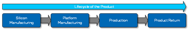
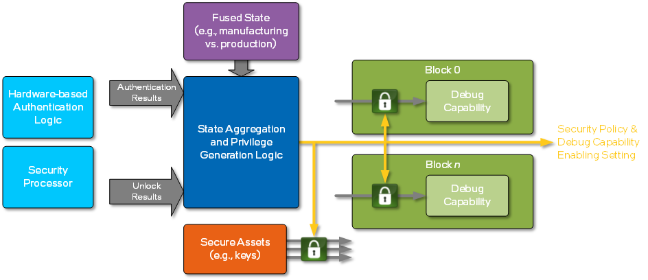
在上电过程中,会有一个窗口期,如果在这个事件段内有Intel授权,那么可以打开调试功能。(There is a limited time during the boot for which this feature can be used by an Intel entity (i.e., an entity authenticated by a per-part Intel key hash stored in the product). The entity must perform the authentication (and unlocking) through this hardware-based mechanism before any secure assets are distributed from its rest location (note: “rest location” refers to where an asset is stored))
/**
  Get the image file buffer data and buffer size by its device path.

  Access the file either from a firmware volume, from a file system interface,
  or from the load file interface.

  Allocate memory to store the found image. The caller is responsible to free memory.

  If FilePath is NULL, then NULL is returned.
  If FileSize is NULL, then NULL is returned.
  If AuthenticationStatus is NULL, then NULL is returned.

  @param[in]       BootPolicy           Policy for Open Image File.If TRUE, indicates
                                        that the request originates from the boot
                                        manager, and that the boot manager is
                                        attempting to load FilePath as a boot
                                        selection. If FALSE, then FilePath must
                                        match an exact file to be loaded.
  @param[in]       FilePath             The pointer to the device path of the file
                                        that is abstracted to the file buffer.
  @param[out]      FileSize             The pointer to the size of the abstracted
                                        file buffer.
  @param[out]      AuthenticationStatus Pointer to the authentication status.

  @retval NULL   FilePath is NULL, or FileSize is NULL, or AuthenticationStatus is NULL, or the file can't be found.
  @retval other  The abstracted file buffer. The caller is responsible to free memory.
**/
VOID *
EFIAPI
GetFileBufferByFilePath (
  IN BOOLEAN                           BootPolicy,
  IN CONST EFI_DEVICE_PATH_PROTOCOL    *FilePath,
  OUT      UINTN                       *FileSize,
  OUT UINT32                           *AuthenticationStatus
  )
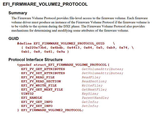
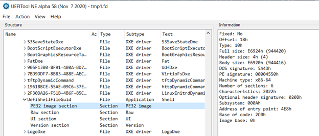
进一步研究,上述函数通过 EFI_FIRMWARE_VOLUME2_PROTOCOL 来完成读取。这个 Protocol 在 PI Spec (并不是 UEFI Spec)中有描述:
/**
  Locates the requested section within a file and returns it in a buffer.

  ReadSection() is used to retrieve a specific section from a file
  within a firmware volume. The section returned is determined
  using a depth-first, left-to-right search algorithm through all
  sections found in the specified file. The output buffer is specified by a double indirection
  of the Buffer parameter. The input value of Buffer is used to
  determine if the output buffer is caller allocated or is
  dynamically allocated by ReadSection(). If the input value of
  Buffer!=NULL, it indicates that the output buffer is caller
  allocated. In this case, the input value of *BufferSize
  indicates the size of the caller-allocated output buffer. If
  the output buffer is not large enough to contain the entire
  requested output, it is filled up to the point that the output
  buffer is exhausted and EFI_WARN_BUFFER_TOO_SMALL is returned,
  and then BufferSize is returned with the size that is required
  to successfully complete the read. All other
  output parameters are returned with valid values. If the input
  value of *Buffer==NULL, it indicates the output buffer is to
  be allocated by ReadSection(). In this case, ReadSection()
  will allocate an appropriately sized buffer from boot services
  pool memory, which will be returned in *Buffer. The size of
  the new buffer is returned in *BufferSize and all other output
  parameters are returned with valid values. ReadSection() is
  callable only from TPL_NOTIFY and below. Behavior of
  ReadSection() at any EFI_TPL above TPL_NOTIFY is
  undefined.

  @param  This                Indicates the EFI_FIRMWARE_VOLUME2_PROTOCOL instance.

  @param NameGuid             Pointer to an EFI_GUID, which indicates the
                              file name from which the requested section
                              will be read.

  @param SectionType          Indicates the section type to return.
                              SectionType in conjunction with
                              SectionInstance indicates which section to
                              return.

  @param SectionInstance      Indicates which instance of sections
                              with a type of SectionType to return.
                              SectionType in conjunction with
                              SectionInstance indicates which
                              section to return. SectionInstance is
                              zero based.

  @param Buffer               Pointer to a pointer to a buffer in which the
                              section contents are returned, not including
                              the section header.

  @param BufferSize           Pointer to a caller-allocated UINTN. It
                              indicates the size of the memory
                              represented by Buffer.

  @param AuthenticationStatus Pointer to a caller-allocated
                              UINT32 in which the authentication
                              status is returned.


  @retval EFI_SUCCESS   The call completed successfully.

  @retval EFI_WARN_BUFFER_TOO_SMALL   The caller-allocated
                                      buffer is too small to
                                      contain the requested
                                      output. The buffer is
                                      filled and the output is
                                      truncated.

  @retval EFI_OUT_OF_RESOURCES  An allocation failure occurred.

  @retval EFI_NOT_FOUND   The requested file was not found in
                          the firmware volume. EFI_NOT_FOUND The
                          requested section was not found in the
                          specified file.

  @retval EFI_DEVICE_ERROR  A hardware error occurred when
                            attempting to access the firmware
                            volume.

  @retval EFI_ACCESS_DENIED The firmware volume is configured to
                            disallow reads. EFI_PROTOCOL_ERROR
                            The requested section was not found,
                            but the file could not be fully
                            parsed because a required
                            GUIDED_SECTION_EXTRACTION_PROTOCOL
                            was not found. It is possible the
                            requested section exists within the
                            file and could be successfully
                            extracted once the required
                            GUIDED_SECTION_EXTRACTION_PROTOCOL
                            is published.

**/
typedef
EFI_STATUS
(EFIAPI * EFI_FV_READ_SECTION)(
  IN CONST  EFI_FIRMWARE_VOLUME2_PROTOCOL *This,
  IN CONST  EFI_GUID                      *NameGuid,
  IN        EFI_SECTION_TYPE              SectionType,
  IN        UINTN                         SectionInstance,
  IN OUT    VOID                          **Buffer,
  IN OUT    UINTN                         *BufferSize,
  OUT       UINT32                        *AuthenticationStatus
);
/**
  Locates a section in a given FFS File and
  copies it to the supplied buffer (not including section header).

  @param  This                       Indicates the calling context.
  @param  NameGuid                   Pointer to an EFI_GUID, which is the
                                     filename.
  @param  SectionType                Indicates the section type to return.
  @param  SectionInstance            Indicates which instance of sections with a
                                     type of SectionType to return.
  @param  Buffer                     Buffer is a pointer to pointer to a buffer
                                     in which the file or section contents or are
                                     returned.
  @param  BufferSize                 BufferSize is a pointer to caller allocated
                                     UINTN.
  @param  AuthenticationStatus       AuthenticationStatus is a pointer to a
                                     caller allocated UINT32 in which the
                                     authentication status is returned.

  @retval EFI_SUCCESS                Successfully read the file section into
                                     buffer.
  @retval EFI_WARN_BUFFER_TOO_SMALL  Buffer too small.
  @retval EFI_NOT_FOUND              Section not found.
  @retval EFI_DEVICE_ERROR           Device error.
  @retval EFI_ACCESS_DENIED          Could not read.
  @retval EFI_INVALID_PARAMETER      Invalid parameter.

**/
EFI_STATUS
EFIAPI
FvReadFileSection (
  IN CONST  EFI_FIRMWARE_VOLUME2_PROTOCOL  *This,
  IN CONST  EFI_GUID                       *NameGuid,
  IN        EFI_SECTION_TYPE               SectionType,
  IN        UINTN                          SectionInstance,
  IN OUT    VOID                           **Buffer,
  IN OUT    UINTN                          *BufferSize,
  OUT       UI


