Loading PEIM 86D70125-BAA3-4296-A62F-602BEBBB9081
Loading PEIM at 0x00007ECF000 EntryPoint=0x00007ECF5A8 DxeIpl.efi
Install PPI: 1A36E4E7-FAB6-476A-8E75-695A0576FDD7
Install PPI: 0AE8CE5D-E448-4437-A8D7-EBF5F194F731
代码在\MdeModulePkg\Core\DxeIplPeim 中,模块入口是如下函数:
/**
  Entry point of DXE IPL PEIM.

  This function installs DXE IPL PPI.  It also reloads
  itself to memory on non-S3 resume boot path.

  @param  FileHandle  Handle of the file being invoked.
  @param  PeiServices Describes the list of possible PEI Services.

  @retval EFI_SUCESS  The entry point of DXE IPL PEIM executes successfully.
  @retval Others      Some error occurs during the execution of this function.

**/
EFI_STATUS
EFIAPI
PeimInitializeDxeIpl (
  IN       EFI_PEI_FILE_HANDLE  FileHandle,
  IN CONST EFI_PEI_SERVICES     **PeiServices
  )
1A36E4E7-FAB6-476A-8E75-695A0576FDD7 是 EFI_PEI_DECOMPRESS_PPI_GUID
0AE8CE5D-E448-4437-A8D7-EBF5F194F731 是EFI_DXE_IPL_PPI_GUID
Loading PEIM 89E549B0-7CFE-449D-9BA3-10D8B2312D71
Loading PEIM at 0x00007ECA000 EntryPoint=0x00007ECA5C8 S3Resume2Pei.efi
Install PPI: 6D582DBC-DB85-4514-8FCC-5ADF6227B147
代码在 \ueficpupkg\universal\acpi\s3resume2pei\中
/**
  Main entry for S3 Resume PEIM.

  This routine is to install EFI_PEI_S3_RESUME2_PPI.

  @param  FileHandle              Handle of the file being invoked.
  @param  PeiServices             Pointer to PEI Services table.

  @retval EFI_SUCCESS S3Resume Ppi is installed successfully.

**/
EFI_STATUS
EFIAPI
PeimS3ResumeEntryPoint (
  IN EFI_PEI_FILE_HANDLE       FileHandle,
  IN CONST EFI_PEI_SERVICES    **PeiServices
  )
动作是安装 EFI_PEI_S3_RESUME2_PPI_GUID 6D582DBC-DB85-4514-8FCC-5ADF6227B147 这个 PPI
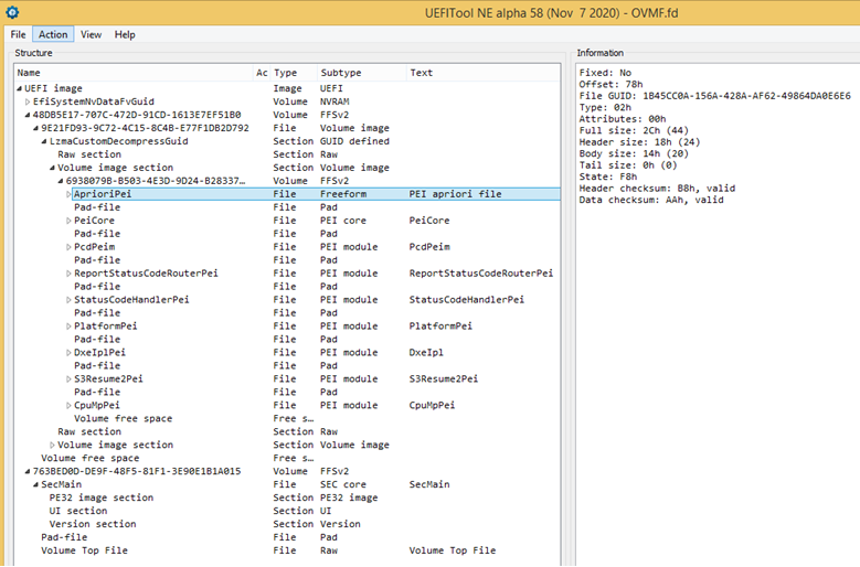
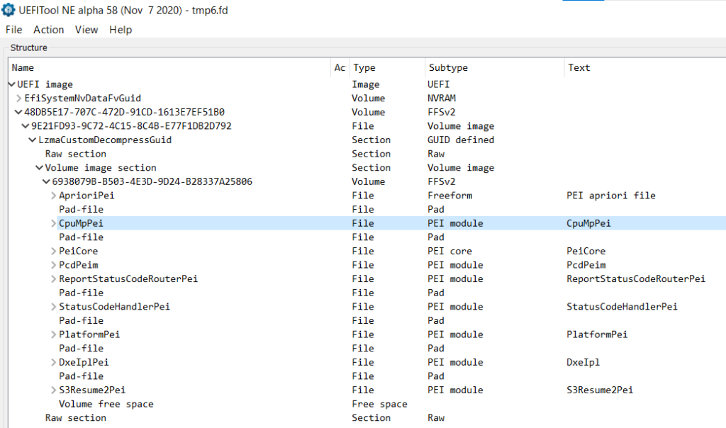
当全部的 PEIM 都加载之后, \mdemodulepkg\core\pei\dispatcher\Dispatcher.c 会执行下面的代码,在第二个FV 中扫描查找 PEIM:
      if (Private->CurrentPeimCount == 0) {
        //
        // When going through each FV, at first, search Apriori file to
        // reorder all PEIMs to ensure the PEIMs in Apriori file to get
        // dispatch at first.
        //
        DiscoverPeimsAndOrderWithApriori (Private, CoreFvHandle);
      }
查找没有找到,输入如下:
DiscoverPeimsAndOrderWithApriori(): Found 0x0 PEI FFS files in the 1th FV
\mdemodulepkg\core\pei\peimain\PeiMain.c 中如下代码执行完毕,至此PEI 阶段就结束了。
  //
  // Call PEIM dispatcher
  //
  PeiDispatcher (SecCoreData, &PrivateData);
接下来查找 IPL PPI
  //
  // Lookup DXE IPL PPI
  //
  Status = PeiServicesLocatePpi (
             &gEfiDxeIplPpiGuid,
             0,
             NULL,
             (VOID **)&TempPtr.DxeIpl
             );
  ASSERT_EFI_ERROR (Status);
通过这个 PPI 进入 DXE 阶段:
  //
  // Enter DxeIpl to load Dxe core.
  //
  DEBUG ((EFI_D_INFO, "DXE IPL Entry\n"));
  Status = TempPtr.DxeIpl->Entry (
                             TempPtr.DxeIpl,
                             &PrivateData.Ps,
                             PrivateData.HobList
                             );
至此开始了新的阶段。