虽然使用了串口很久,但是一直没有深入研究波形。最近看了一篇介绍【参考1】,随手用示波器抓了一下波形。
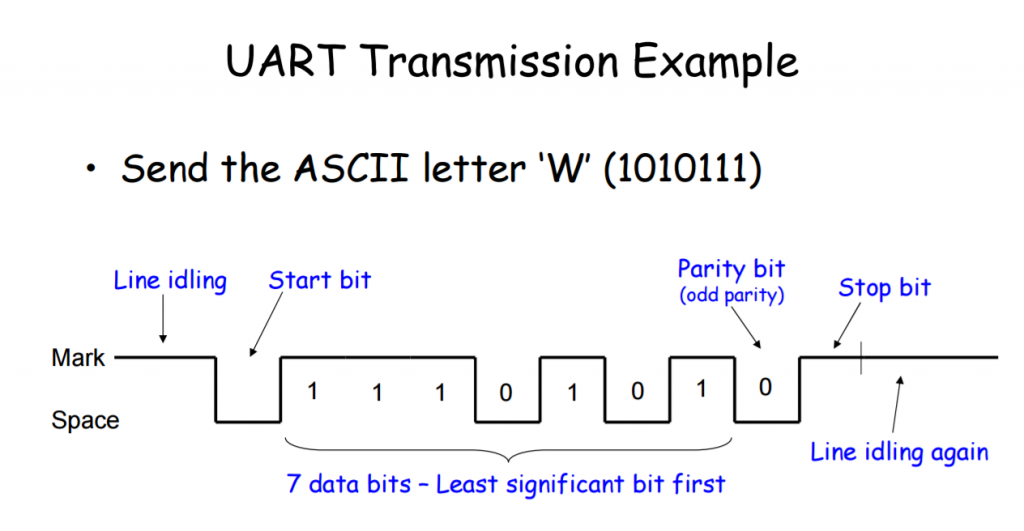
下面是资料中提到的例子。在无数据传输时,串口总线上应该是高电平。当有数据传输时,首先会拉低一个时钟周期,这是 Start Bit。之后是有用的数据,长度是根据双方约定好的。最后可以跟着一个校验位(也可以没用),最终用一个拉高的时钟周期表示传输完成,这是Stop Bit。然后总线继续拉高处于Idle状态。

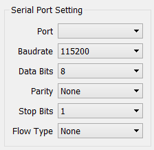
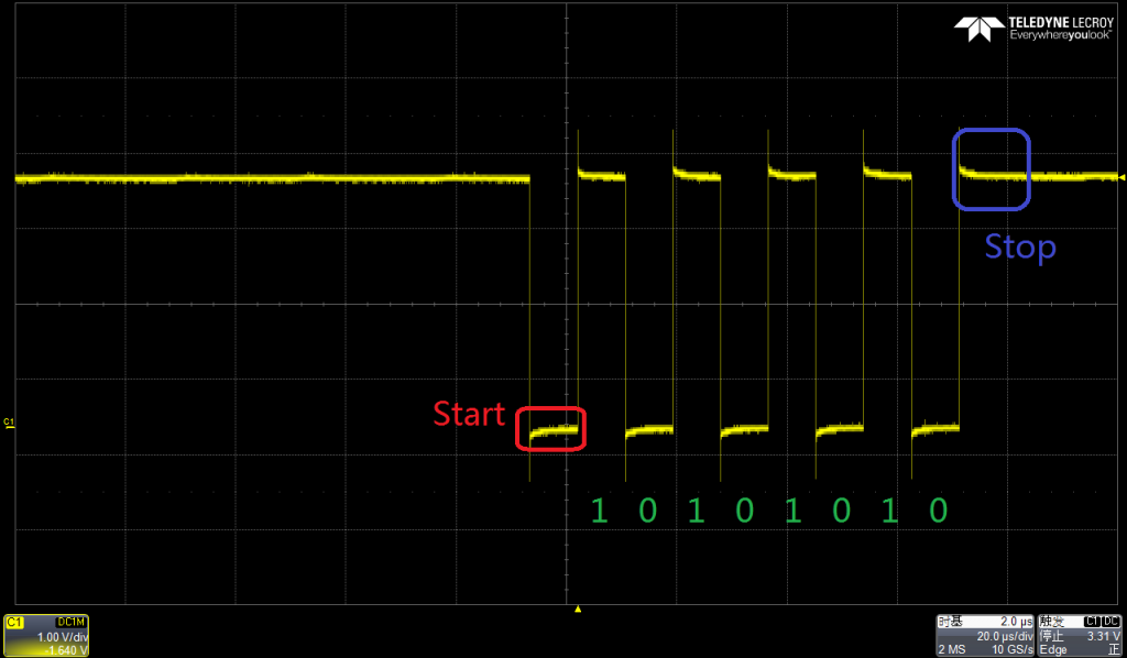
下面示波器抓取的实际波形,双方的通讯设置如下:

发送0xAA

最后附上一个常用的对 0x3F8 初始化的代码段
#define PORT 0x3f8 /* COM1 */
void init_serial() {
outb(PORT + 1, 0x00); // Disable all interrupts
outb(PORT + 3, 0x80); // Enable DLAB (set baud rate divisor)
outb(PORT + 0, 0x01); // Set divisor to 1 (lo byte) 115200 baud
outb(PORT + 1, 0x00); // (hi byte)
outb(PORT + 3, 0x03); // 8 bits, no parity, one stop bit
outb(PORT + 2, 0xC7); // Enable FIFO, clear them, with 14-byte threshold
outb(PORT + 4, 0x0B); // IRQs enabled, RTS/DSR set
}
参考:
1.http://www.unm.edu/~zbaker/ece238/slides/UART.pdf
