PWRTest

PwrTest 是一款微软提供的用于Power Loop 测试的工具【参考1】,可以用于 ModernStandby或者 S3/S4 循环测试。它位于 WDK中,安装后可以在C:\Program Files (x86) \Windows Kits\ 目录中找到(建议在这这个目录下直接搜索)。

用法非常简单:

  1. 使用管理员权限打开 cmd 窗口
  2. Pwrtest + 参数即可

例如:测试S4睡眠并且唤醒 100次

pwrtest /sleep  /s:4 /c:100  

下面是运行 pwrtest /? 得到的帮助信息:

Usage: pwrtest /scenario [/scenario_options] [/common_options]

scenario
  Name                Description                                     Min OS Req
  ------------------------------------------------------------------------------
  sleep               run sleep/resume transitions                    Win7
  battery             battery information and monitoring              Win7
  info                system power information                        Win7
  es                  thread execution state monitoring               Win7
  idle                power idle monitoring                           Win7
  ppm                 processor power management monitoring           Win7
  timer               system timer resolution monitoring              Win7
  disk                disk idle monitoring                            Win7
  device              device idle monitoring                          Win7
  monitor             monitor dim/blank monitoring (user idle)        Win7
  requests            power request monitoring                        Win7
  thermal             ACPI thermal zone monitoring                    Win7
  processidle         monitor and force idle/background tasks to run  Win7
  cs                  run connected standby transitions               Win8
  platidle            platform idle statistics monitoring             Win8
  ppmidlecontrol      veto/un-veto processor idle states              Win10 RS5
  platformidlecontrol veto/un-veto platform idle states               Win10 RS5
  directedfx          run Directed FX tests on a device               Win10 19H1

scenario_options
  To see available scenario options type: pwrtest.exe /scenario /?
  Example: pwrtest.exe /sleep /?

common_options
  /lf:folder          folder for the log files
                      For example, c:\myfolder or \\server\share
                      Default log location is the same folder as pwrtest.exe
  /ln:name            name for the log files and the ETW trace session name.
                      Log file extensions added automatically (.wtl, .xml, etc.)
                      Default name is pwrtestlog.
  /etwbuffersize:n    n indicates ETW buffer size in KB if larger than default.
                      Default is current page size or 256KB (whichever is
                      greater).
  /etwminbuffers:n    n indicates the minimum number of buffers allocated for
                      the ETW session if larger than the minimum of 2 per
                      logical processor.
                      Default is 2 per logical processor
  /etwmaxbuffers:n    n indicates the maximum number of buffers allocated for
                      the ETW session if larger than the minimum of 2 per
                      logical processor and larger than etwminbuffers.
                      Default is etwminbuffers + 20.
  /delaywrite         when specified, log data is buffered in memory to reduce
                      disk writes.  Affects all log types including ETL.


Execution Requirements:
  -must run from an administrator/elevated command prompt in order to support
   ETW tracing
  -must run natively (WoW64 not supported) in order to support ETW tracing
  -group policy settings put in place by your system administrator may
   interfere with some scenarios that need to temporarily modify power
   setting values (such as the sleep scenario)

这是 10.0.22621.1 WDK 自带的pwrtest。

有需要测试 S3 S4 MS Loop的朋友可以考虑使用这款工具进行测试。

参考:

1. https://learn.microsoft.com/zh-cn/windows-hardware/drivers/devtest/pwrtest

ESP32 S3 I2C 从机测试

测试了 ESP32 S3 的 I2C 从机功能, 使用的是ESP32 S3 DevKitC-1 如下:

C:\Users\YOUNAME\AppData\Local\Arduino15\packages\esp32\hardware\esp32\2.0.4\libraries\Wire\examples\WireSlave
#include "Wire.h"

#define I2C_DEV_ADDR 0x55

uint32_t i = 0;

void onRequest(){
  Wire.print(i++);
  Wire.print(" Packets.");
  Serial.println("onRequest");
}

void onReceive(int len){
  Serial.printf("onReceive[%d]: ", len);
  while(Wire.available()){
    Serial.write(Wire.read());
  }
  Serial.println();
}

void setup() {
  Serial.begin(115200);
  Serial.setDebugOutput(true);
  Wire.onReceive(onReceive);
  Wire.onRequest(onRequest);
  Wire.begin((uint8_t)I2C_DEV_ADDR);

#if CONFIG_IDF_TARGET_ESP32
  char message[64];
  snprintf(message, 64, "%u Packets.", i++);
  Wire.slaveWrite((uint8_t *)message, strlen(message));
#endif
}

void loop() {

}

打开 Debug 开关,运行之后提示:

Attempting to boot anyway...
entry 0x403c98d8
[   104][I][esp32-hal-i2c-slave.c:234] i2cSlaveInit(): Initialising I2C Slave: sda=8 scl=9 freq=100000, addr=0x55
[   104][D][esp32-hal-i2c-slave.c:486] i2c_slave_set_frequency(): Fifo thresholds: rx_fifo_full = 28, tx_fifo_empty = 4

就是说:SDA 是8 Pin, SCL 是9 Pin,特别注意默认频率是 100K.

之后 I2C 工具设置如下:

设置发送数据  aa(地址) 31 32 33 34 35 36 37

ESP32 端收到的数据为

onReceive[7]: 1234567

测试使用的工具是志明电子出品的 USB 转SPI/I2C 调试工具。

修改 LattePanda BIOS 在 ACPI 中增加一个设备

这次我们实验在 LattePanda 的 DSDT ACPI Table 中增加一个自定义设备。

首先,我们需要解压原版IFWI 中的 ACPI 模块出来。对于这次的 LattePanda来说,DSDT 是特别放在一个独立的 FFS中。

直接解压之:

使用十六进制工具打开可以看到就是 DSDT Table

因为目前的 ACPI 版本和之前的比如 TigerLake 有一些差别,因此,这里需要使用最新版本的 iASL 进行反编译:

反编译结果在 dsdt.dsl 文件中。使用文本编辑工具打开后,在最后加入我们自定义的设备:

之后再重新编译为 AML

对于这个文件,使用如下命令打包为一个 SECTION,对应的 GenSec.exe工具来自 EDK2 的源代码:

GenSec -s EFI_SECTION_RAW -o DSDT.raw dsdt.aml

接下来再使用 GenFFS 把 dsdt.raw 打包生成一个 FFS文件:

GenFfs -t EFI_FV_FILETYPE_FREEFORM -g C118F50D-391D-45F4-B3D3-11BC931AA56D -o new.ffs -oi dsdt.raw

接下来,我们使用新生成的这个 new.ffs替换位于03:02-01 (Index F9)处的FFS

最终我们就得到了一个替换过DSDT的新的 IFWI 文件:

本文提到的文件和工具可以在这里下载:

修改好后烧录进入 Windows即可看到设备管理器中多了一个设备,测试的视频在

https://www.bilibili.com/video/BV1GU411d7v1/?pop_share=1&vd_source=cf6121716e06cb669a27c10276f9c920

Blinker 实时数据的Demo

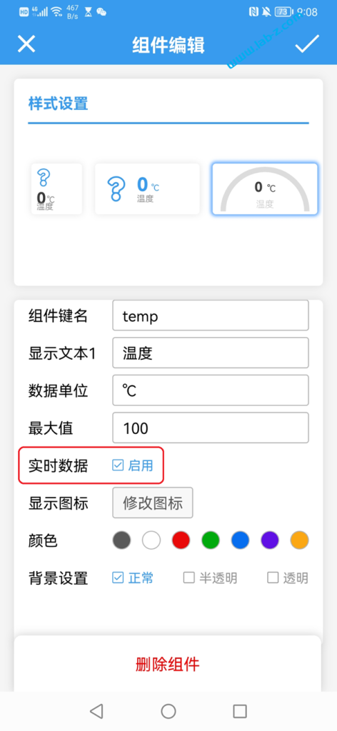
有些情况下,我们需要查看即时数据,比如当前的加热温度。对于这种情况,可以使用 blinker 的“实时数据”功能。启用方法非常简单:在控件界面上选中“实时数据”即可。

下面是一个测试代码,每隔2秒生成一组温度湿度数据,显示在串口上同时发送到 Blinker 的服务器上。之后打开 Blinker 的APP 即可看到实时数值。

#define BLINKER_WIFI

#include <Blinker.h>

char auth[] = "你的Key";
char ssid[] = "你家WIFI名";
char pswd[] = "你家WIFI密码";

BlinkerNumber HUMI("humi");
BlinkerNumber TEMP("temp");


uint32_t read_time = 0;

float Humidity=0, Temperature=0;

void rtData()
{
    Blinker.sendRtData("temp", Humidity);
    Blinker.sendRtData("humi", Temperature);
    Blinker.printRtData();
}

void setup()
{
    Serial.begin(115200);
    BLINKER_DEBUG.stream(Serial);
    BLINKER_DEBUG.debugAll();
    pinMode(LED_BUILTIN, OUTPUT);
    digitalWrite(LED_BUILTIN, LOW);

    Blinker.begin(auth, ssid, pswd);
    Blinker.attachRTData(rtData);
    
}

void loop()
{

    Blinker.run();

    if (read_time == 0 || (millis() - read_time) >= 2000)
    {
        read_time = millis();  

        BLINKER_LOG("Humidity: ", Humidity, " %");
        BLINKER_LOG("Temperature: ", Temperature, " *C");

        if (Temperature>50.0) {Temperature=0;} else {Temperature=Temperature+0.4;}
        if (Humidity>50.0) {Humidity=0;} else {Humidity=Humidity+0.9;}
    }
}

运行之后可以在 Blinker 上看到温湿度的实时变化:

在 LattePanda BIOS 插入自定义模块

UEFI 的一个优点是模块化,意思是你可以编写一个模块,编译后能够插入到已有的BIOS中并且执行。在此之前,每个 IVB 实现方式差异巨大,除了按照 PCI ROM 这种特别形式插入几乎没有办法实现通用。这次演示的就是在 EDK2环境下编写一个DXE 模块,然后插入到LattePanda中。

首先进行代码的设计,仿照\OvmfPkg\8254TimerDxe这个模块就可以写好。

代码非常简单,入口是InitializezMessage () 函数,进入之后注册OnMyReadyToBoot函数,当ReadyToBootEvent事件时触发之。代码如下:

EFI_STATUS
EFIAPI
InitializezMessage (
  IN EFI_HANDLE        ImageHandle,
  IN EFI_SYSTEM_TABLE  *SystemTable
  )
{
  EFI_STATUS  Status=EFI_SUCCESS;
  EFI_EVENT   ReadyToBootEvent;

  DEBUG ((DEBUG_INFO, "UPassword DXE Loaded\n"));

  //
  // Register the event to reclaim variable for OS usage.
  //
  EfiCreateEventReadyToBootEx (
    TPL_NOTIFY,              
    OnMyReadyToBoot, 
    NULL,
    &ReadyToBootEvent  
    );  

  return Status;
}

这样,当BIOS 准备启动的时候就是跳入OnMyReadyToBoot() 函数,执行,在函数中只是循环显示一段字符串。

/**
  On Ready To Boot Services Event notification handler.

  Notify SMM variable driver about the event.

  @param[in]  Event     Event whose notification function is being invoked
  @param[in]  Context   Pointer to the notification function's context

**/
VOID
EFIAPI
OnMyReadyToBoot (
  IN      EFI_EVENT                         Event,
  IN      VOID                              *Context
  )
{
  DEBUG ((EFI_D_INFO, "Invoke OnMyReadyToBoot\n"));
  
  for (UINTN i=0;i<5;i++) {
	gST->ConOut->OutputString(gST->ConOut,L"\r\n delay from www.lab-z.com\r\n");
	gBS->Stall(1000000UL);
  }
	
  gBS->CloseEvent (Event);
}

然后将其加入编译,在\OvmfPkg\OvmfPkgX64.dsc 修改如下:

!ifdef $(CSM_ENABLE)
  OvmfPkg/8259InterruptControllerDxe/8259.inf
  OvmfPkg/8254TimerDxe/8254Timer.inf
!else
  OvmfPkg/LocalApicTimerDxe/LocalApicTimerDxe.inf
!endif
  #LABZ_Debug_Start
  OvmfPkg/ zMessage / zMessage.inf
  #LABZ_Debug_End 
  OvmfPkg/IncompatiblePciDeviceSupportDxe/IncompatiblePciDeviceSupport.inf
  OvmfPkg/PciHotPlugInitDxe/PciHotPlugInit.inf

在 \OvmfPkg\OvmfPkgX64.fdf 修改如下:

!ifdef $(CSM_ENABLE)
  INF  OvmfPkg/8259InterruptControllerDxe/8259.inf
  INF  OvmfPkg/8254TimerDxe/8254Timer.inf
!else
  INF  OvmfPkg/LocalApicTimerDxe/LocalApicTimerDxe.inf
!endif
#LABZ_Debug_Start
INF  OvmfPkg/ zMessage / zMessage.inf
#LABZ_Debug_End
INF  OvmfPkg/IncompatiblePciDeviceSupportDxe/IncompatiblePciDeviceSupport.inf
INF  OvmfPkg/PciHotPlugInitDxe/PciHotPlugInit.inf
INF  MdeModulePkg/Bus/Pci/PciHostBridgeDxe/PciHostBridgeDxe.inf

使用如下命令在 QEMU 上测试:

qemu-system-x86_64 -bios ovmf.fd  -net none 

可以看到在启动过程中屏幕上输出了定义的字符串。

生成的FFS文件在\Build\OvmfX64\DEBUG_VS2019\FV\Ffs\00002237-2024-0513-A7F3-1449F9E0E4BDzMessage目录中(为了方便查找,我们在 INF中指定模块的 GUID 是 0000开头的)。文件名是 00002237-2024-0513-A7F3-1449F9E0E4BD.ffs。这就是我们编译后的模块。

接下来,使用 MMTOOL打开 LattePanda官方提供的 IFWI 文件:

我们选择在Volume 03:02-01 Index 137 的地方插入(理论上 UEFI模块在BIOS中的位置不影响加载顺序,这里只是为了方便查找随便选择的位置),下面就是完成后的结果:

最后,使用“Save Image as…”重新保存命名为 zMessage.fd,然后烧录到 LattePanda上即可。

本文提到的 UEFI 源代码:

UEFI 源代码生成的 FFS 文件:

最终加入模块的 LattePanda 的IFWI:

虚拟电池

之前我设计过一款虚拟电池【参考1】,美中不足的是这个虚拟电池是基于 WDTF。如果想使用就必须安装微软的 WDTF 框架,但是你无法知道WDTF 对系统有多少影响。

因此,最近请天杀帮忙重新设计了一款虚拟电池驱动,用于 Windows 10/11 。驱动可以在系统中虚拟出一块电池,配合应用程序可以设置是否有外部电源(AC/DC),以及设置当前电量。实现简单,可以广泛用于系统功耗测试和一些电源相关功能的评估。

使用方法:

1.运行 Driver 中 Install.bat 安装驱动
2.使用 Batset.exe 在命令下下设置虚拟电池属性。例如: BatSet AC 50 将会切换为 AC Mode, 50% 电量。BatSet DC 19 将会切换为 DC Mode, 19% 电量。
3.运行 Driver 下的 remove.bat 即可移除驱动

参考:
1.https://www.lab-z.com/zvb/

工作的测试视频:

https://www.bilibili.com/video/BV1ef421175X

WordPress上传图片错误:不是合法的JSON响应

最近更换服务器之后,在编写文章的时候上传图片经常会出现“WordPress上传图片错误:不是合法的JSON响应”的问题。虽然收到报错,但是在媒体中确实也能看到上传后的图片因此一直没有在意,对付着在用。

最近有点时间,于是静下来仔细研究了一下这个问题。

第一步,打开Wordpress 的 Debug log,但是发生现象的时候Log中没有 Error;

第二步,关闭 WordPress 的相关插件,现象仍然存在;

第三步,使用 Chrome 的调试功能,发现出现现象的时候,浏览器收到了 Server Internal 500 错误,因此,这个问题和 WordPress没有关系,应该和服务器有关系;

最终,找到了错误原因:PHP 设置的临时目录指向了错误的目录,修改之后就正常了。

遇到类似问题的朋友不妨试试看。

VirtualBox 关闭 Secure Boot

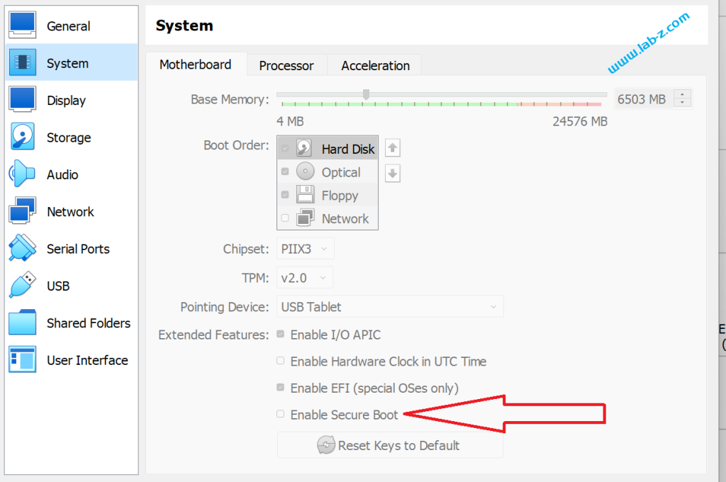
默认情况下 VirtualBox 创建的虚拟机 SecureBoot 是 Enabled。可以通过按住 ctrl 从菜单重启的方式进入 BIOS Setup

选择 “User a device”

选择 “UiApp” 就能够进入 Setup 界面了

具体选项在“Device Manager->Secure Boot Configuration->Attempt Secure Boot”,去掉对勾即可:

可以看到此时 Secure Boot 已经关闭了

此外,在创建虚拟机的地方也有一个选项,不过看起来没起作用。

记事本.LOG 的秘密

Windows 自带的记事本(Notepad)是一个非常方便易用的文本编辑工具。虽然我从Window3.1开就使用这个软件,但是最近刚知道它有一个特别的功能:如果在文本开头写入  .LOG ,那么保存之后每次使用记事本打开这个文件都会自动添加当前的日期和时间。

这个功能是记事本代码实现的,在https://github.com/vxiiduu/NotepadEx 这个项目上可以看到(这个项目代码来自泄露的 Windows XP 代码)。在其中的 npfile.c 文件中可以看到检测 “.LOG”字样的代码:

       // null terminate it.  Safe even if nChars==0 because it is 1 TCHAR bigger
       *(lpch+nChars)= (TCHAR) 0;
   
       // Set 'fLog' if first characters in file are ".LOG"
       fLog= *lpch++ == TEXT('.') &amp;&amp; *lpch++ == TEXT('L') &amp;&amp;
             *lpch++ == TEXT('O') &amp;&amp; *lpch == TEXT('G');

之后,同样文件还有根据标志位进行动作的代码:

    /* If file starts with ".LOG" go to end and stamp date time */
    if (fLog)
    {
       SendMessage( hwndEdit, EM_SETSEL, (WPARAM)nChars, (LPARAM)nChars);
       SendMessage( hwndEdit, EM_SCROLLCARET, 0, 0);
       InsertDateTime(TRUE);
}

为了验证猜想,我对上述代码进行修改,判断条件之后除了增加时间再增加一段我自定义的字符串:

    /* If file starts with ".LOG" go to end and stamp date time */
    if (fLog)
    {
       SendMessage( hwndEdit, EM_SETSEL, (WPARAM)nChars, (LPARAM)nChars);
       SendMessage( hwndEdit, EM_SCROLLCARET, 0, 0);
       InsertDateTime(TRUE);
	   //LABZ_Debug_Start
	   TCHAR szMsg[] = TEXT("www.lab-z.com");
	   SendMessage(hwndEdit, EM_REPLACESEL, TRUE, (LPARAM)szMsg);
	   //LABZ_Debug_End
}

编译之后用生成的 EXE 打开 TEXT 文件,可以看到除了时间,还增加了我自定义的代码。

未修改的完整项目可以在这类下载(就是 Github 上的源代码):

工作的视频

https://www.bilibili.com/video/BV1Ym421H7zk

BMX60 旋转一只兔子

一直以来我想通过传感器让现实世界中的物体控制电脑中的物体姿态,最近入手了DFRobot的BMX160九轴加速度传感器模块【参考1】。

所谓9轴指的是三个加速度轴,三个地测轴和三个陀螺仪轴。简单的介绍一下需要了解的物理知识:首先,如果物体发生运动,那么在三个轴方向会出现加速度,那么我们可以知道它运动的指向,此外比较特别的是因为重力影响,所以一直会存在一个加速度G;接下来因为地磁的存在(指南针的基本原理),我们可以通过地磁轴得到相对于地磁的方向;最后陀螺因为惯性,它会一直保持指向,因此陀螺仪的轴可以用来反映当前时间和上一个时间姿态区别,得到诸如角速度这种方向。

很明显,如果单纯得到上面的9个参数,我们仍然难以用其中的一组描述物体当前的状态,因此,需要经过算法处理得到当前的状态。这个过程叫做“姿态解算”,同样也叫做姿态分析、姿态估计、姿态融合。姿态解算是根据IMU(惯性测量单元)数据(陀螺仪、加速度计、地磁计等)求解出飞行器的空中姿态,所以也叫做IMU数据融合。【参考2】

因为本人能力有限,无力应对复杂的数学,因此这里通过硬件和现成的库来解决。

DFRobot的BMX160引脚定义如下:

丝印功能描述
VCC电源正极
GND电源负极
SCLI2C时钟线
SDAI2C数据线
CSBBMX160协议选择引脚
INIT1BMX160外部中断1
INIT2BMX160外部中断2
ADDRI2C地址选择

需要特别注意的是 CSB 是一个 SPI 和 I2C 选择引脚,这次我们使用I2C, 因此只需要链接 VCC GND  SCL 和 SDA 引脚即可。我是用的是 ESP32 FireBeetle 进行测试,

连接好之后推荐使用 DFRobot 的BMX160库先进行测试【参考4】,确保串口能看到输出。

硬件部分非常简单,接下来要进行软件方面的编写。同样,还需要了解一些关于姿态描述的基本知识。描述姿态的主要方法有两种:欧拉角和四元数。下图是欧拉角的直观描述。三个参数分别是航向角、俯仰角和横滚角。

需要注意的是对于欧拉角有两种:动态和静态欧拉角。动态欧拉角指的是轴跟着物体姿态旋转,比如,下图中物体圆转之后蓝色XYZ坐标系发生了变化,变成了红色的XYZ,如果再次旋转,那么航向角、俯仰角和横滚角都是要相对于红色XYZ的。静态欧拉角的话,就是一直使用蓝色 XYZ。从资料上看,通常我们提到的欧拉角都是动态欧拉角。但是很多三维设计软件使用的是静态欧拉角。

欧拉角非常直观容易理解。但是在使用中,这种描述方法会存在“万向节死锁(gimbal lock)”的问题。就是说在一些特别的角度,两个轴重合了,然后再也不会分开,继续旋转时欧拉角只有2个参数会变。B站有很多视频讲述这个问题有兴趣的朋友可以看看。

为了解决这个问题,引入了四元数的概念。四元数没有欧拉角那么直观,也非常难以理解。

这次的目标是使用 Adafruit 提供的库和网站来直观的实现旋转一只兔子。

首先安装 BMX160 和 Adafruit_Sensor库;之后,烧录下面的程序:

#include <Wire.h>
#include <Adafruit_Sensor.h>
#include <Mahony_BMX160.h>
#include <Madgwick_BMX160.h>
#include <DPEng_BMX160.h>


// Create sensor instance.
DPEng_BMX160 dpEng = DPEng_BMX160(0x160A, 0x160B, 0x160C);

// Mag calibration values are calculated via ahrs_calibration example sketch results.
// These values must be determined for each baord/environment.
// See the image in this sketch folder for the values used
// below.

// Offsets applied to raw x/y/z mag values
float mag_offsets[3]            = { 9.83F, 4.42F, -6.97F };

// Soft iron error compensation matrix
float mag_softiron_matrix[3][3] = { {  0.586,  0.006,  0.001 },
                                    {  0.006,  0.601, -0.002 },
                                    {  0.001,  -0.002,  2.835 } };

float mag_field_strength        = 56.33F;

// Offsets applied to compensate for gyro zero-drift error for x/y/z
float gyro_zero_offsets[3]      = { 0.0F, 0.0F, 0.0F };

// Mahony is lighter weight as a filter and should be used
// on slower systems
Mahony_BMX160 filter;
//Madgwick_BMX160 filter;

void setup()
{
  Serial.begin(115200);

  // Wait for the Serial Monitor to open (comment out to run without Serial Monitor)
  // while(!Serial);

  Serial.println(F("DPEng AHRS Fusion Example")); Serial.println("");

  // Initialize the sensors.
  if(!dpEng.begin(BMX160_ACCELRANGE_4G, GYRO_RANGE_250DPS))
  {
    /* There was a problem detecting the BMX160 ... check your connections */
    Serial.println("Ooops, no BMX160 detected ... Check your wiring!");
    while(1);
  }
  
  filter.begin();
}

void loop(void)
{
  sensors_event_t accel_event;
  sensors_event_t gyro_event;
  sensors_event_t mag_event;

  // Get new data samples
  dpEng.getEvent(&accel_event, &gyro_event, &mag_event);

  // Apply mag offset compensation (base values in uTesla)
  float x = mag_event.magnetic.x - mag_offsets[0];
  float y = mag_event.magnetic.y - mag_offsets[1];
  float z = mag_event.magnetic.z - mag_offsets[2];

  // Apply mag soft iron error compensation
  float mx = x * mag_softiron_matrix[0][0] + y * mag_softiron_matrix[0][1] + z * mag_softiron_matrix[0][2];
  float my = x * mag_softiron_matrix[1][0] + y * mag_softiron_matrix[1][1] + z * mag_softiron_matrix[1][2];
  float mz = x * mag_softiron_matrix[2][0] + y * mag_softiron_matrix[2][1] + z * mag_softiron_matrix[2][2];

  // Apply gyro zero-rate error compensation
  float gx = gyro_event.gyro.x + gyro_zero_offsets[0];
  float gy = gyro_event.gyro.y + gyro_zero_offsets[1];
  float gz = gyro_event.gyro.z + gyro_zero_offsets[2];

  // Update the filter
  filter.update(gx, gy, gz,
                accel_event.acceleration.x, accel_event.acceleration.y, accel_event.acceleration.z,
                mx, my, mz,
				mag_event.timestamp);

  // Print the orientation filter output
  // Note: To avoid gimbal lock you should read quaternions not Euler
  // angles, but Euler angles are used here since they are easier to
  // understand looking at the raw values. See the ble fusion sketch for
  // and example of working with quaternion data.
  float roll = filter.getRoll();
  float pitch = filter.getPitch();
  float heading = filter.getYaw();
  //Serial.print(millis());
  Serial.print("Orientation: ");
  Serial.print(heading);
  Serial.print(",");
  Serial.print(pitch);
  Serial.print(",");
  Serial.println(roll);

  delay(100);
}

在串口管理器中看到输出表明工作正常之后就可以进行下一步。

我们需要网页读取串口数据,在 Chrome 上地址栏输入 chrome://flags,打开 Experimental Web Platform features:

之后,打开 https://adafruit.github.io/Adafruit_WebSerial_3DModelViewer/ 页面,设置波特率为 115200 , 同时选择“Euler Angles”:

接下来选择使用的串口(记得要关闭 Arduino 的串口,否则无法打开)

然后你就可以随心所欲的旋转,屏幕上的兔子会跟着你的板卡转动。

参考:

  1. https://www.dfrobot.com.cn/goods-2947.html
  2. https://www.cnblogs.com/codeit/p/15832606.html
  3. https://wiki.dfrobot.com.cn/_SKU_SEN0373_BMX160_9-axis_sensor_module
  4. https://github.com/DFRobot/DFRobot_BMX160
  5. https://learn.adafruit.com/adafruit-bno055-absolute-orientation-sensor/webserial-visualizer