当我们在代码中直接定义浮点数如下所示时,会遇到 Warning C4305: ‘initializing’: truncation from ‘double’ to ‘float’
float f1=0.12,f2=0.34;
这个警告的意思是:你定义的是一个 double 而非 float 类型。
解决方法有如下2种:
1.更换类型为 double
2.在数值后面加上 “f” 例如:
float f1=0.12f,f2=0.34f;
当我们在代码中直接定义浮点数如下所示时,会遇到 Warning C4305: ‘initializing’: truncation from ‘double’ to ‘float’
float f1=0.12,f2=0.34;
这个警告的意思是:你定义的是一个 double 而非 float 类型。
解决方法有如下2种:
1.更换类型为 double
2.在数值后面加上 “f” 例如:
float f1=0.12f,f2=0.34f;
前面介绍了使用 ESP32 S3 播放 SPINOR 中的内容,美中不足的是 SPI 容量有限无法播放长视频。这次的作品能够实现读取和发送SD卡中的JPG 图片,从而实现长时间的播放。
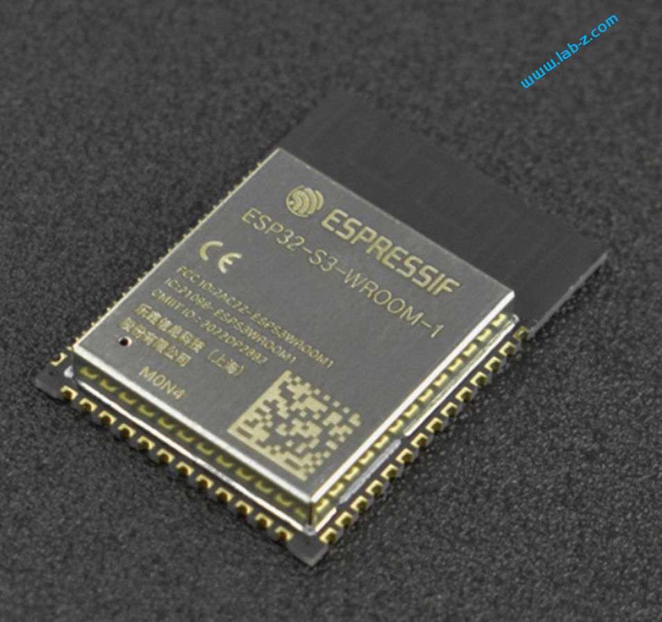
实验是基于DFRobot 的ESP32-S3-WROOM-1-N4模组(DFR0896)【参考1】来实现的,需要注意的是:这个模组没有 PSRAM,项目中需要关闭PSRAM。为了读取 SD 卡,需要使用上一次设计的 OV2640 Shield,其中的 SD 卡是4线模式。
插入SD卡,板子堆叠起来即可工作。接下来着手代码设计。
和之前相比,代码改动较大,主要修改有:
    // By default, SD card frequency is initialized to SDMMC_FREQ_DEFAULT (20MHz)
    // For setting a specific frequency, use host.max_freq_khz (range 400kHz - 40MHz for SDMMC)
    // Example: for fixed frequency of 10MHz, use host.max_freq_khz = 10000;
    sdmmc_host_t host = SDMMC_HOST_DEFAULT();
	host.max_freq_khz = 20000;

    // This initializes the slot without card detect (CD) and write protect (WP) signals.
    // Modify slot_config.gpio_cd and slot_config.gpio_wp if your board has these signals.
    sdmmc_slot_config_t slot_config = SDMMC_SLOT_CONFIG_DEFAULT();

    slot_config.width = 4;

    // On chips where the GPIOs used for SD card can be configured, set them in
    // the slot_config structure:
	//ZivDebug_Start
	slot_config.clk = 48;
	slot_config.cmd = 37;
	slot_config.d0 = 10;
	slot_config.d1 = 14;
	slot_config.d2 = 35;
	slot_config.d3 = 36;
	//ZivDebug_End
主要是指定工作频率为 20Mhz (如果你发现读取的时候会出错,不妨尝试降低这个频率);工作模式为4线;另外指定了使用的SD 信号控制线和数据线。
3.接下来,我们修改之前 camera_fb_get_cb() 函数中访问 SPI 的代码,修改为访问SD 卡
char buffer[64];
	struct stat file_stat;
	int  filesize;
	FILE *fd = NULL;
	sprintf(buffer,MOUNT_POINT"/m/%04d.jpg",PicIndex);
	ESP_LOGI(TAG, "p1 %s %d",buffer,PicIndex);

	if (stat(buffer, &file_stat) == -1) {
		ESP_LOGI(TAG, "%d frame in %llums",
				PicIndex,
				(esp_timer_get_time()/1000-Elsp));
		Elsp=esp_timer_get_time()/1000;
		PicIndex=0;
		sprintf(buffer,MOUNT_POINT"/m/%04d.jpg",PicIndex);
	} else {PicIndex++;}
	fd = fopen(buffer, "r");

    fseek(fd, 0, SEEK_END);
    filesize = ftell(fd);
    rewind(fd);
	ESP_LOGI(TAG, "send %d",filesize);

	fread(&PicBuffer, 1, filesize, fd);
	s_fb.uvc_fb.buf = PicBuffer;
	s_fb.uvc_fb.len=filesize;
	fclose(fd);
基本思路是:尝试访问 m\NNNN.jpg 这样的文件,如果文件存在,那么取得他的大小,如果该文件不存在,说明最后一帧处理完成需要从第一张再开始。之后将文件内容读取到PicBuffer作为返回值返回给调用者。
目前测试的是 320X240 的内容,速度上完全没有问题。
参考:
这次带来一个好玩的 ESP32 项目:虚拟摄像头,就是将ESP32 S3 的板子烧录之后,系统中会出现一个USB摄像头,打开Camera后能够看到播放出来的视频。
下面介绍具体的实现方式。
目前 Arduino ESP32 尚不支持 USB Camera,因此,这次的项目是基于IDF 来完成的。特别注意:对于硬件有如下要求:
1.必须是 ESP32 S2或者 S3,其他型号的ESP32 目前不支持原生USB编程,所以只能使用 S2 或者 S3;
2.必须带有 PSRAM,因为这个项目是根据Demo 修改而来,Demo 要求带有 PSRAM。我对编译环境不熟悉,这部分没有修改, 理论上移除对于 Camera 的支持即可在没有 PSRAM 的板子上使用;
3.必须是 16MB 的 ESP32 模块,如果想在更小容量的板子上使用,可以删除项目中的JPEG素材缩减体积,同时修改项目配置为 4MB 或者8MB.
如果你对ESP32 IDF环境比较熟悉,可以修改去掉上面提到的2的限制;同样的,可以删除部分图片使得4MB的ESP32 也可以支持。如果你无法做到这两点,可以像我一样使用 ESP32 S3 EYS 兼容版。
先介绍一下如何使用我的代码:
安装 ESP32 IDF 编译环境
2.下载安装 esp-iot-solution,解压后放在c: 根目录下
3.尝试编译C:\esp-iot-solution\examples\usb\device\usb_webcam 确保编译环境无误
4.基本的命令有
a. 编译命令 idf.py build (特别注意编译时需要联网)
b.烧录 idf.py -p COM端口 flash
c.串口监视器 idf.py -p COM端口 monitor
d.上述指令可以放在一起,例如:
idf.py -p com6 build flash monitor
e.监视器可以使用 ctrl+] 退出
f.项目配置 idf.py menuconfig ()
5.将usb_webcam1 解压到C:\esp-iot-solution\examples\usb\device目录下
使用 idf.py -p com6 build flash monitor 编译后会自动烧录然后打开串口监视器。
6.打开系统自带的相机程序,切换到ESP32 摄像头即可看到播放内容
上面介绍了如何直接使用代码,接下来介绍一下项目基本实现原理。
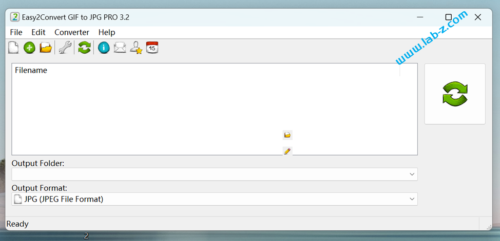
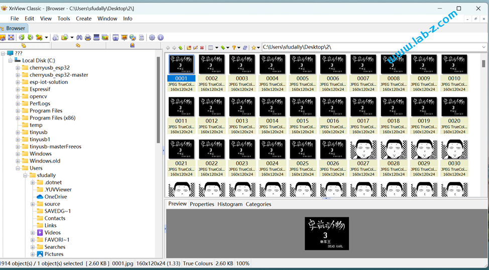
5. 使用 XnView 处理上面的 JPG 文件。需要将所有的图片名为为 0000、0001…..0XXX 这种名称;同样使用这个软件将所有的图片都修改为 320*240 大小。
修改的代码主要部分在动作就是按照孙旭检查 SPIFFS 中,storage 下面是否有XXXX.jpg 这样的文件,如果有就读取出来作为摄像头数据上报,如果XXXX.JPG 不存在,那么就说明读取完毕,再从 0000开始。
static uvc_fb_t* camera_fb_get_cb(void *cb_ctx)
{
	s_fb.uvc_fb.timestamp.tv_usec++;

	char buffer[64];
	struct stat file_stat;
	int  filesize;
	FILE *fd = NULL;
	sprintf(buffer,"/storage/%04d.jpg",PicIndex);
	ESP_LOGI(TAG, "p1 %s %d",buffer,PicIndex);

	if (stat(buffer, &file_stat) == -1) {
		PicIndex=0;
		ESP_LOGI(TAG, "ZivHer2");
		sprintf(buffer,"/storage/%04d.jpg",PicIndex);
	} else {PicIndex++;}
	fd = fopen(buffer, "rb");
	ESP_LOGI(TAG, "ZivHer3");
    fseek(fd, 0, SEEK_END);
    filesize = ftell(fd);
    rewind(fd);
	ESP_LOGI(TAG, "send %d",filesize);

	fread(&PicBuffer, 1, filesize, fd);
	s_fb.uvc_fb.buf = PicBuffer;
	s_fb.uvc_fb.len=filesize;
	fclose(fd);
	vTaskDelay(pdMS_TO_TICKS(100));
    return &s_fb.uvc_fb;
}
ESP32 官方提供了一个USB 摄像头的例子,但是他们使用带有 PSRAM 的ESP32,经过研究,不支持 PSRAM的模组可以通过修改代码的方式实现相同的功能。本文以ESP32-S3-WROOM-1-N4模组(DFR0896)【参考1】为例,介绍实现方式。
首先使用这个模组制作一个底板【参考2】
接下来设计给摄像头模块使用的连接器,摄像头选择的是微雪电子的 OV2640模块。OV2640是OmniVision公司生产的一颗1/4寸的CMOS UXGA(1632*1232)图像传感器; 支持自动曝光控制、自动增益控制、自动白平衡、自动消除灯光条纹等自动控制功能。 UXGA最高15帧/秒,SVGA可达30帧,CIF可达60帧; 支持图像压缩,即可直接输出JPEG图像数据.
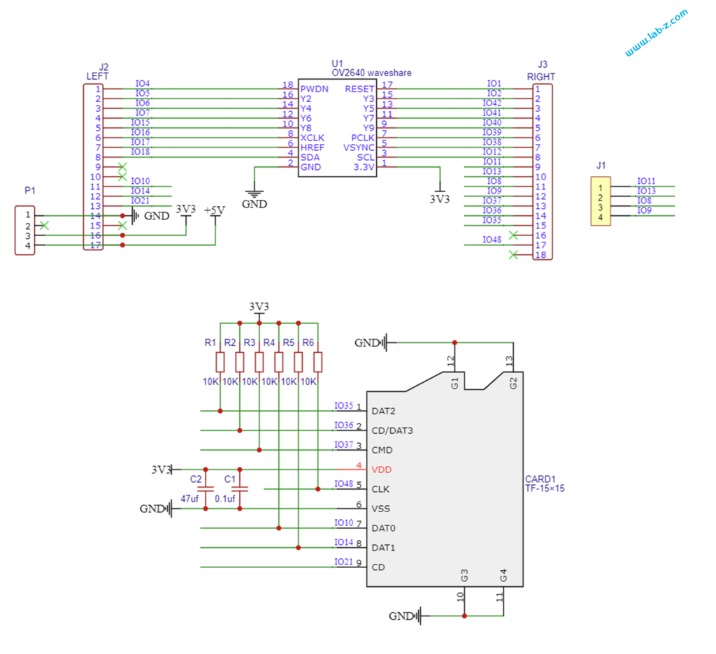
设计的 OV2640 Shield电路图如下,除了一个用于连接摄像头之外,还预留了一个 SD 卡座,让 ESP32 S3 板子有读写 SD 数据的能力。

PCB 设计如下:
3D预览结果:
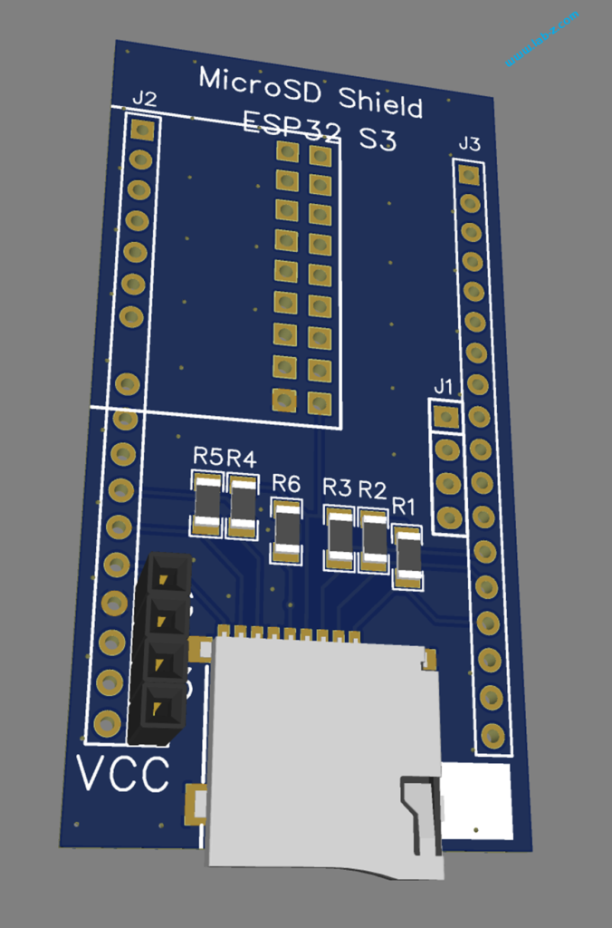
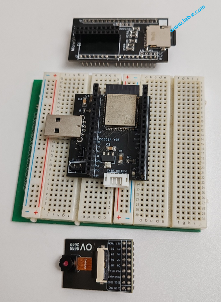
焊接好之后的板子和 ESP32 S3 以及 OV2640 的照片:

接下来就可以进行代码的编写了。
通过 idf.py menuconfig 设定OV2640 的引脚,然后去掉PSRAM 的支持。.fb_location = CAMERA_FB_IN_DRAM 这里指定摄像头使用 ESP32 内置 RAM 即可。
连接之后即可工作。
工作的测试视频在
本文提到的电路图和PCB 在:
源代码在:
参考:
C++还有两个重要的函数:new 和 delete。根据《UEFI 原理与编程》 10.2.6 讲述,我们需要自行实现函数。
上述书籍对应的代码提供了 new 和 delete 的实现,可以看到基本的思路就是使用 gSt-> BootServices ->AllocatePool 分配和gSt-> BootServices->FreePool回收内存:
#include <UEFI/UEFI.h>
#include <type_traits>

EFI_SYSTEM_TABLE* gSt;

typedef UINTN size_t;

void *  operator new( size_t Size )
{
    void       *RetVal;
    EFI_STATUS  Status;

    if( Size == 0) {
        return NULL;
    }

    Status = gSt-> BootServices ->AllocatePool( EfiLoaderData, (UINTN)Size, &RetVal);
    if( Status != EFI_SUCCESS) {
        RetVal  = NULL;
    }
    return RetVal;
}


void *  operator new[]( size_t cb )
{
    void *res = operator new(cb);
    return res;
}

void operator delete( void * p )
{
  if(p != NULL)
    (void) gSt-> BootServices->FreePool (p);
}

void operator delete[]( void * p )
{
    operator delete(p);
}

void printInt(EFI_SIMPLE_TEXT_OUTPUT_PROTOCOL* conOut, int value) {
	CHAR16 out[32];
	CHAR16* ptr = out;
	static_assert(std::is_unsigned_v<char16_t>);
	if (value == 0)
	{
		conOut->OutputString(conOut, u"0");
		return;
	}

	ptr += 31;
	*--ptr = 0;
	int tmp = value;// >= 0 ? value : -value;

	while (tmp)
	{
		*--ptr = '0' + tmp % 10;
		tmp /= 10;
	}

	if (value < 0) *--ptr = '-';
	conOut->OutputString(conOut, ptr);
}

EFI_STATUS
efi_main(EFI_HANDLE /*image*/, EFI_SYSTEM_TABLE* systemTable)
{
	gSt=systemTable;
	int *p=new int;

	*p=123;

	printInt(gSt->ConOut,*p);
	gSt->ConOut->OutputString(gSt->ConOut, u"\r\n");

	delete p;

	return EFI_SUCCESS;
}
运行之后可以在屏幕上看到 123 的字样。
接下来实验使用 new 和 delete 创建对象的情况,基本的代码如下:
class Time {

public:
	Time() {//构造函数
		gSt->ConOut->OutputString(gSt->ConOut, u"Init\n\r");
	}
	~Time(){//析构函数
		gSt->ConOut->OutputString(gSt->ConOut, u"Destroy\n\r");
    }

private:
	int _hour;
	int _min;
	int _sec;
};

EFI_STATUS
efi_main(EFI_HANDLE /*image*/, EFI_SYSTEM_TABLE* systemTable)
{
	gSt=systemTable;
	Time *myTime=new Time;
	delete myTime;
	return EFI_SUCCESS;
}
运行结果如下:
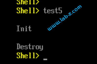
可以看到,当我们 new 创建对象的时候,自动运行了 Time 的构造函数。构造函数的作用是:当该类对象被创建的时候,编译系统对象分配内存空间,并自动调用该构造函数,由构造函数完成成员的初始化工作,故:构造函数的作用:初始化对象的数据成员。同样的还有一个“析构函数”,用于做一些清理的洞动作。
有兴趣的朋友可以进一步阅读如下文件:
似乎国内使用 Windows IIS 架设 Wordpress 的用户非常少,以至于我遇到问题通常只能在英文网站中搜索到需要的信息。最近遇到了Wordpress 的网站健康提示“模组 GD未被安装或已被禁用”的问题。经过搜索答案非常简单:PHP 的配置文件 php.ini 中默认禁止了 GD2, 但是实际上内置的是GD。因此将对应的那一行取消注释,并且将 GD2 修改为 GD 即可。
用户可以从串口输入一个在1-255的数字,然后在D9上输出对应的占空比,PWM 频率是 62.5KHz。
需要注意:如果需要输出全低或者全高需要修改代码。
// Leonardo 测试,在 D9 上输出从串口给定的PWM 值
void setup() {
  Serial.begin(115200);

  /* Set speakers as outputs */
  DDRB   |= ((1 << 6) | (1 << 5));

  /* PWM speaker timer initialization */
  TCCR1A  = ((1 << WGM10) | (1 << COM1A1) | (1 << COM1A0)
             | (1 << COM1B1) | (1 << COM1B0)); // Set on match, clear on TOP
  TCCR1B  = ((1 << WGM12) | (1 << CS10));  // Fast 8-Bit PWM, F_CPU speed

}

void loop() {
  if (Serial.available() > 0) {
    //读取一个整数
    int Value = Serial.parseInt();
    Serial.print("Get:");
    Serial.println(Value);
    if (Value > 255)||(Value==0) {
      Serial.println("Please input a 0<number<256");
    } else {
      OCR1A = Value;
    }
  }
}
近期将切换服务器,因此可能出现服务器不稳定的情况,预计持续一周左右。
在此期间不会更新网站内容。
感谢支持,预祝春节快乐!
2024年1月19日,新服务器上线,相比之前增加了带宽和硬盘容量。
我们看到的最简单的 C++ 代码是如下形式:
int main()
{
    std::cout << "Hello World!\n";
}
问题来了:如何在 UEFI 下面实现这种形式的代码?根据【参考1】,cout << n; 中,<< 是个运算符,n 是个变量,运算符应该接的是变量,所以 cout是个变量,但是在C++中这种高级变量叫做对象。cout 是一个对象。
因此,我们可以通过定义 cout 这个对象,然后定义 << 这个运算符即可。完整代码如下:
#include <UEFI/UEFI.h>
#include <type_traits>

#define EFI_ERROR(status) ((status) != EFI_SUCCESS)

EFI_SYSTEM_TABLE* gSystemTable;

void printInt(int value) {
	CHAR16 out[32];
	CHAR16* ptr = out;
	static_assert(std::is_unsigned_v<char16_t>);
	if (value == 0)
	{
		gSystemTable->ConOut->OutputString(gSystemTable->ConOut, u"0");
		return;
	}

	ptr += 31;
	*--ptr = 0;
	int tmp = value;// >= 0 ? value : -value;

	while (tmp)
	{
		*--ptr = '0' + tmp % 10;
		tmp /= 10;
	}

	if (value < 0) *--ptr = '-';
	gSystemTable->ConOut->OutputString(gSystemTable->ConOut, ptr);
}

class ostream {
public:
    void operator<<(int x);
};

void ostream::operator<<(int x) {
    printInt(x);
    return ;
}

ostream cout;

EFI_STATUS
efi_main(EFI_HANDLE /*image*/, EFI_SYSTEM_TABLE* systemTable)
{
	gSystemTable=systemTable;
	cout << 122;
	gSystemTable->ConOut->OutputString(gSystemTable->ConOut, u"\r\n");
	return EFI_SUCCESS;
}
运行结果如下:
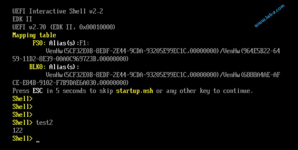
已经非常像了。接下来还有一个 std 的问题。这个可以通过 Namespace来实现。“编写程序过程中,名称(name)可以是符号常量、变量、函数、结构、枚举、类和对象等等。工程越大,名称互相冲突性的可能性越大。另外使用多个厂商的类库时,也可能导致名称冲突。为了避免,在大规模程序的设计中,以及在程序员使用各种各样的 C++ 库时,这些标识符的命名发生冲突,标准 C++ 引入关键字 namespace(命名空间/名字空间/名称空间),可以更好地控制标识符的作用域。
例如,我们在 C 语言中,通过 static 可以限制名字只在当前编译单元内可见,在 C++ 中我们通过 namespace 来控制对名字的访问。”【参考2】
修改代码如下形式:
namespace std {

class ostream {
public:
    void operator<<(int x);
};

void ostream::operator<<(int x) {
    printInt(x);
    return ;
}
ostream cout;

}
namespace 是C++中的关键字,用来定义一个命名空间,语法格式为:
namespace name{
    //variables, functions, classes
}
name是命名空间的名字,它里面可以包含变量、函数、类、typedef、#define 等,最后由{ }包围【参考3】。
我们就可以直接使用 std::cout << 122; 这种形式了。接下来,还有如何实现 std::cout << 122 << 13; 有兴趣的朋友可以继续研究。
参考:
最近因为测试需要一款能够占用内存的软件,于是求助天杀,请他帮忙编写了一个能够占用指定内存大小的代码。
在使用之前因为微软的限制需要对 Windows进行一些设定:
1.运行 gpedit.msc ,打开“本地组策略编辑器”
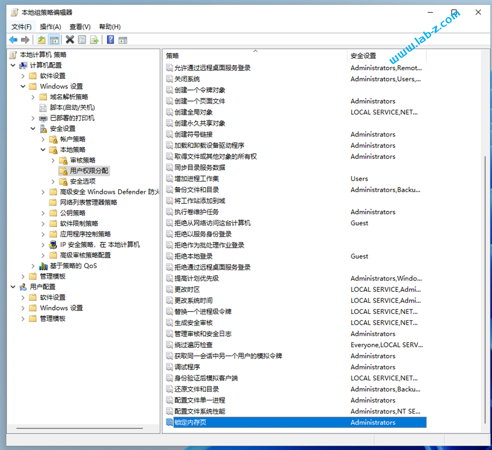
2.找到位于 “计算机配置”-> “Windows设置”->“安全设置”->“本地策略”->“用户权限分配”中的“锁定内存页”
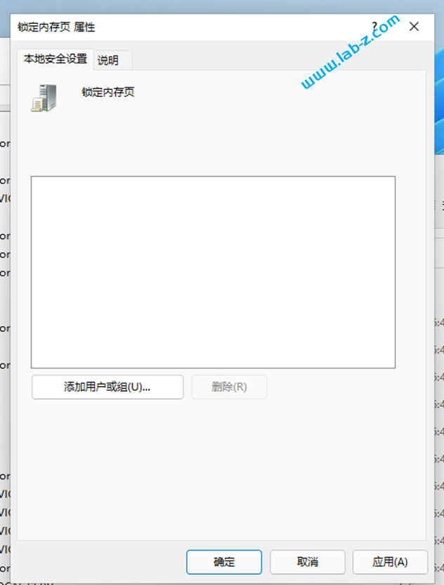
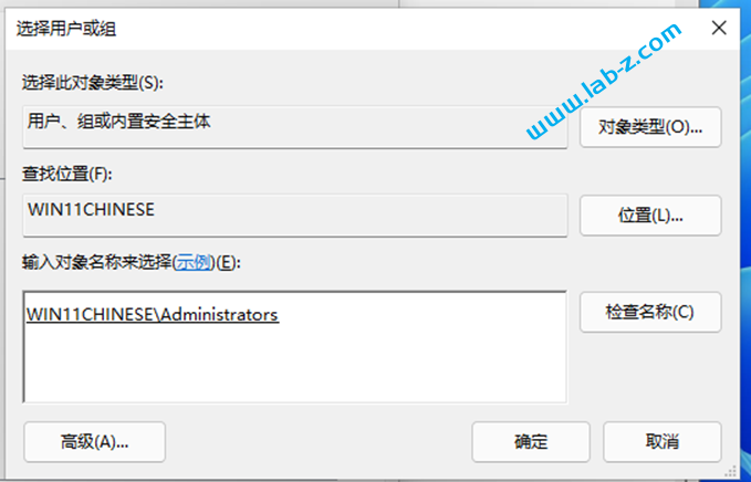
3.接下来的目标是将“Administrators”加入其中。点击“添加用户组或组”。
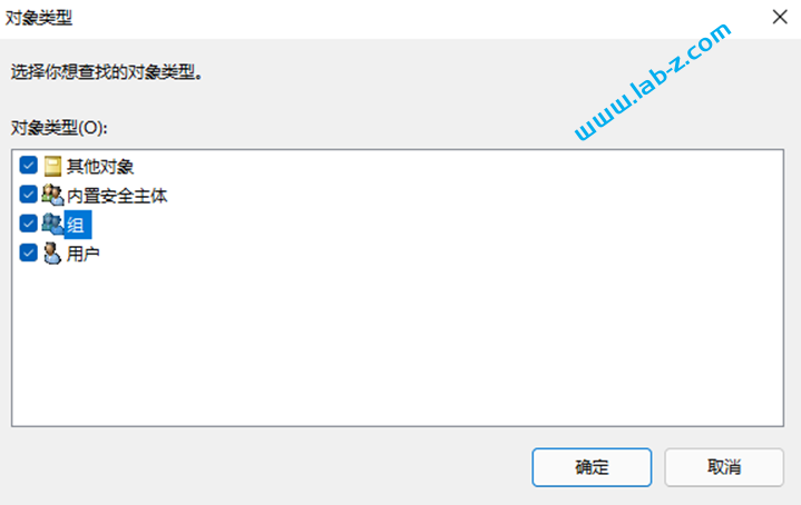
4.点击“对象类型”按钮,勾选其中的“组”
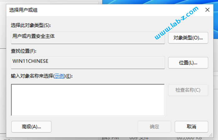
5. 之后在“输入对象名称来选择”中输入“Administrators”(注意末尾有“s”),然后点击“检查名称”按钮
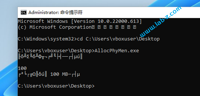
6.重启系统后以管理员权限打开 cmd 串口。这时候你可能遇到无法正常显示汉字的问题,例如:
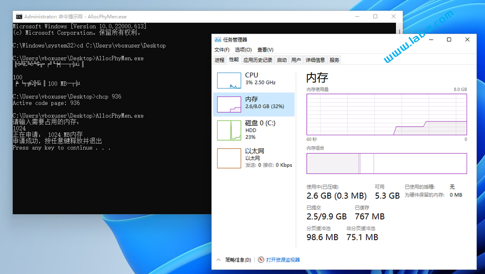
7. 使用 chcp 936 切换到中文,再次运行即可,程序运行之后要求你输入的需要占用的内存,比如,这里输入 1024 ,可以在任务管理器中看到内存使用率升高了。按任意键之后释放占用的内存。
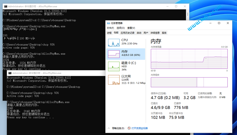
8.还可以运行多个程序方便进行内存调整
源代码和可执行程序: