/**
Retrieves the current value of a 64-bit free running performance counter.
The counter can either count up by 1 or count down by 1. If the physical
performance counter counts by a larger increment, then the counter values
must be translated. The properties of the counter can be retrieved from
GetPerformanceCounterProperties().
@return The current value of the free running performance counter.
**/
UINT64
EFIAPI
GetPerformanceCounter (
VOID
);
/**
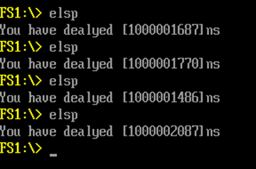
Converts elapsed ticks of performance counter to time in nanoseconds.
This function converts the elapsed ticks of running performance counter to
time value in unit of nanoseconds.
@param Ticks The number of elapsed ticks of running performance counter.
@return The elapsed time in nanoseconds.
**/
UINT64
EFIAPI
GetTimeInNanoSecond (
IN UINT64 Ticks
);
/**
  Retrieves the current value of a 64-bit free running performance counter.
  The counter can either count up by 1 or count down by 1. If the physical
  performance counter counts by a larger increment, then the counter values
  must be translated. The properties of the counter can be retrieved from
  GetPerformanceCounterProperties().
  @return The current value of the free running performance counter.
**/
UINT64
EFIAPI
GetPerformanceCounter (
  VOID
  );
/**
  Converts elapsed ticks of performance counter to time in nanoseconds.
  This function converts the elapsed ticks of running performance counter to
  time value in unit of nanoseconds.
  @param  Ticks     The number of elapsed ticks of running performance counter.
  @return The elapsed time in nanoseconds.
**/
UINT64
EFIAPI
GetTimeInNanoSecond (
  IN      UINT64  Ticks
  );
CacheMaintenanceLib|MdePkg/Library/BaseCacheMaintenanceLib/BaseCacheMaintenanceLib.inf
  TimerLib|UefiCpuPkg/Library/CpuTimerLib/BaseCpuTimerLib.inf
###################################################################################################
#
# Components Section - list of the modules and components that will be processed by compilation
#