串口是非常有效和廉价的Debug手段,在开发中,几乎所有的UEFI 主板都会支持串口,本文介绍如何在Shell下面实现 串口通讯。
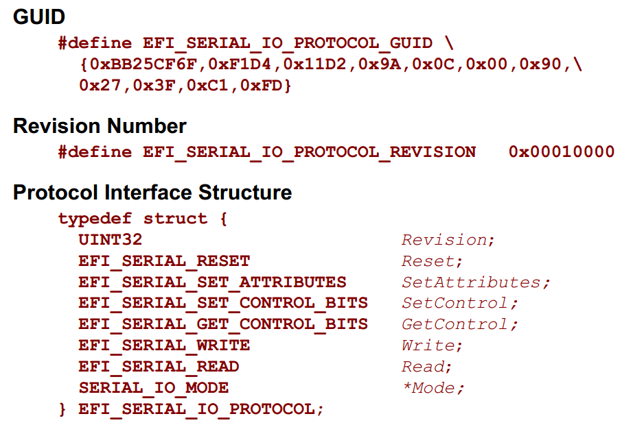
与之相关的是 EFI_SERIAL_IO_PROTOCOL,这个 Protocol 的定义可以在 UEFI Spec【参考1】中看到:
代码如下:
#include  <Uefi.h>
#include  <Library/UefiLib.h>
#include  <Library/ShellCEntryLib.h>

#include  <Protocol/SerialIo.h>

extern EFI_BOOT_SERVICES         *gBS;
extern EFI_SYSTEM_TABLE	     *gST;
extern EFI_RUNTIME_SERVICES 	 *gRT;

EFI_GUID gEfiSerialIoProtocolGuid = { 0xBB25CF6F, 0xF1D4, 0x11D2, { 0x9A, 0x0C, 0x00, 0x90, 0x27, 0x3F, 0xC1, 0xFD }};

EFI_STATUS
DumpSetting(
  IN UINT64    BaudRate,
  IN UINT32    ReceiveFifoDepth,
  IN UINT32    Timeout,
  IN EFI_PARITY_TYPE    Parity,
  IN UINT8              DataBits,
  IN EFI_STOP_BITS_TYPE StopBits)
{
	Print(L"   Timeout: [%d]\n",Timeout);
	Print(L"   BaudRate:[%ld]\n",BaudRate);
	Print(L"   DataBits:[%d]\n",DataBits);
	Print(L"   Parity:  [%d]\n",Parity);
	Print(L"   StopBits:[%d]\n",StopBits);
	Print(L"   ReceiveFifoDepth:[%d]\n",ReceiveFifoDepth);

	return EFI_SUCCESS;
}


int
EFIAPI
main (
  IN int Argc,
  IN char **Argv
  )
{
    EFI_STATUS          			Status;
	EFI_SERIAL_IO_PROTOCOL 			*Serial;
	CHAR8 							*Textbuf1 = "www.lab-z.com  waiting.........\n";
	CHAR8 							*Textbuf2 = "Continue............\n";
	CHAR8 							*Textbuf3 = "12345678";
	CHAR16 							*Textbuf4 = L"                               ";
	UINTN							BufferSize;
	EFI_TIME						TimeStart,TimeEnd;

    Status = gBS->LocateProtocol(
						&gEfiSerialIoProtocolGuid,
						NULL,
						(VOID **)&Serial);


    if (EFI_ERROR(Status)) {
		    Print(L"Cannot find EFI_SERIAL_IO_PROTOCOL \r\n");
            return Status;
	}

	Print(L"Current Settings:\n");
	DumpSetting(
			Serial->Mode->BaudRate,
			Serial->Mode->ReceiveFifoDepth,
			Serial->Mode->Timeout,
			Serial->Mode->Parity,
			Serial->Mode->DataBits & 0xFF,
			Serial->Mode->StopBits);

	// Baudrate 115200,Data Bits=8,Parity=None,Stop Bits=1,Flow Type= None
	Status=Serial->SetAttributes(  Serial,
							115200,
							Serial->Mode->ReceiveFifoDepth,
							Serial->Mode->Timeout,
							NoParity,
							8,
							OneStopBit);
	if (Status!=EFI_SUCCESS) {
		Print(L"[%d], %r",Status,Status);
	}

	Print(L"New Settings:\n");
	DumpSetting(
			Serial->Mode->BaudRate,
			Serial->Mode->ReceiveFifoDepth,
			Serial->Mode->Timeout,
			Serial->Mode->Parity,
			Serial->Mode->DataBits & 0xFF,
			Serial->Mode->StopBits);

	BufferSize=AsciiStrLen(Textbuf1);
	Serial->Write(Serial,&BufferSize,Textbuf1);

	gRT->GetTime(&TimeStart,NULL);
	TimeEnd=TimeStart;

	while ((TimeEnd.Hour - TimeStart.Hour) * 60 * 60
			+ (TimeEnd.Minute - TimeStart.Minute)*60
			+ (TimeEnd.Second - TimeStart.Second) < 30)
	  {
		 BufferSize=AsciiStrLen(Textbuf3);
		 Status=Serial->Read(Serial,&BufferSize,Textbuf3);
		 if ((Status==EFI_SUCCESS) && (BufferSize!=0))
			{
				Print(L"read [%d] %s\n",BufferSize,AsciiStrToUnicodeStr(Textbuf3,Textbuf4));
			}
			gRT->GetTime(&TimeEnd,NULL);
	  }

	BufferSize=AsciiStrLen(Textbuf2);
	Serial->Write(Serial,&BufferSize,Textbuf2);

    return EFI_SUCCESS;
}
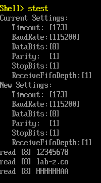
上面程序的基本流程:首先检查一下串口设置,打印在屏幕上,然后设置为我们通常使用的 115200。最后测试用 Write从 Shell 下发送数据出来,再尝试用Read接收数据。
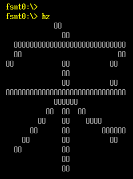
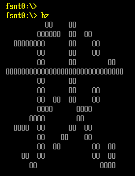
程序运行结果:
完整代码下载:
SerialTest
特别注意:Shell 使用 Read 只能接收固定长度的数据。比如: Read(Serial,8,Textbuf) 那么只能接收8个字符,如果你只输入了7个bytes,不会有反应;如果输入了9个bytes,那么只能收到前面8个。目前不清楚为什么有这样的限制。
另外,对于普通的串口,使用GetControl 获得的当前的状态中并没有当前串口的发送接收状态。定义的 EFI_SERIAL_INPUT_BUFFER_EMPTY和EFI_SERIAL_OUTPUT_BUFFER_EMPTY 应该是给存在对应线路的串口使用的,是一种硬件线路的标志。如果你只用了 TX RX GND , 这里的状态是没有意义的。
参考:
1. UEFI Spec 2.4 P476