有一个网友提出一个问题“现在要进行一个0.4us的延时,发现不管怎么调都只能调到15us,根本达不到要求,我用的芯片是MEGA32U4-AU,外部晶振是16MHz,求见解!!!!!”
我试验了一下,最终的程序如下:
const int PinA =  13;
void setup() {
  pinMode(PinA, OUTPUT);
  digitalWrite(PinA,LOW);
}

void loop() {
  PORTB = B100000; //digitalWrite(PinA,HIGH);
  PORTB = B000000; //digitalWrite(PinA,LOW);
    for (long zdelay=0;zdelay<9; zdelay++) {
    __asm__("nop\n\t");
  }
  PORTB = B100000; //digitalWrite(PinA,HIGH);
  PORTB = B000000; //digitalWrite(PinA,LOW);
  PORTB = B100000; //digitalWrite(PinA,HIGH);
  PORTB = B000000;  //digitalWrite(PinA,LOW);
}
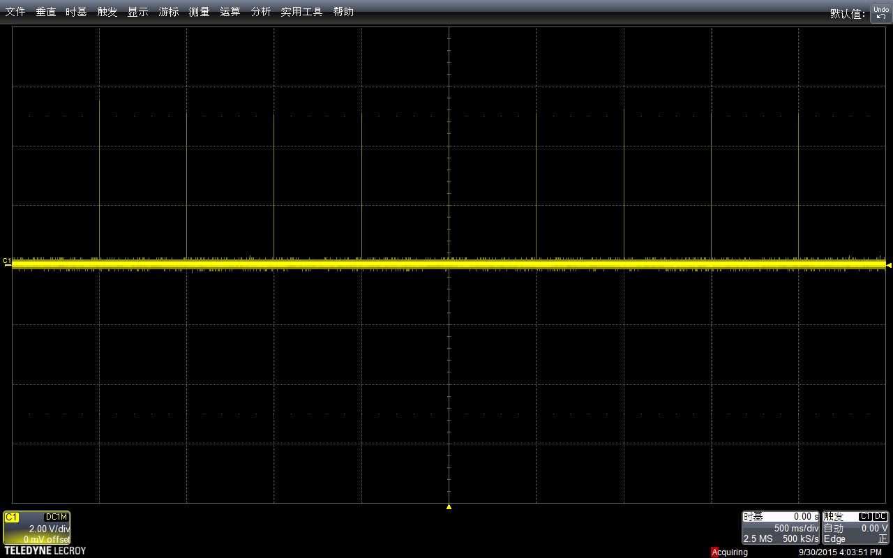
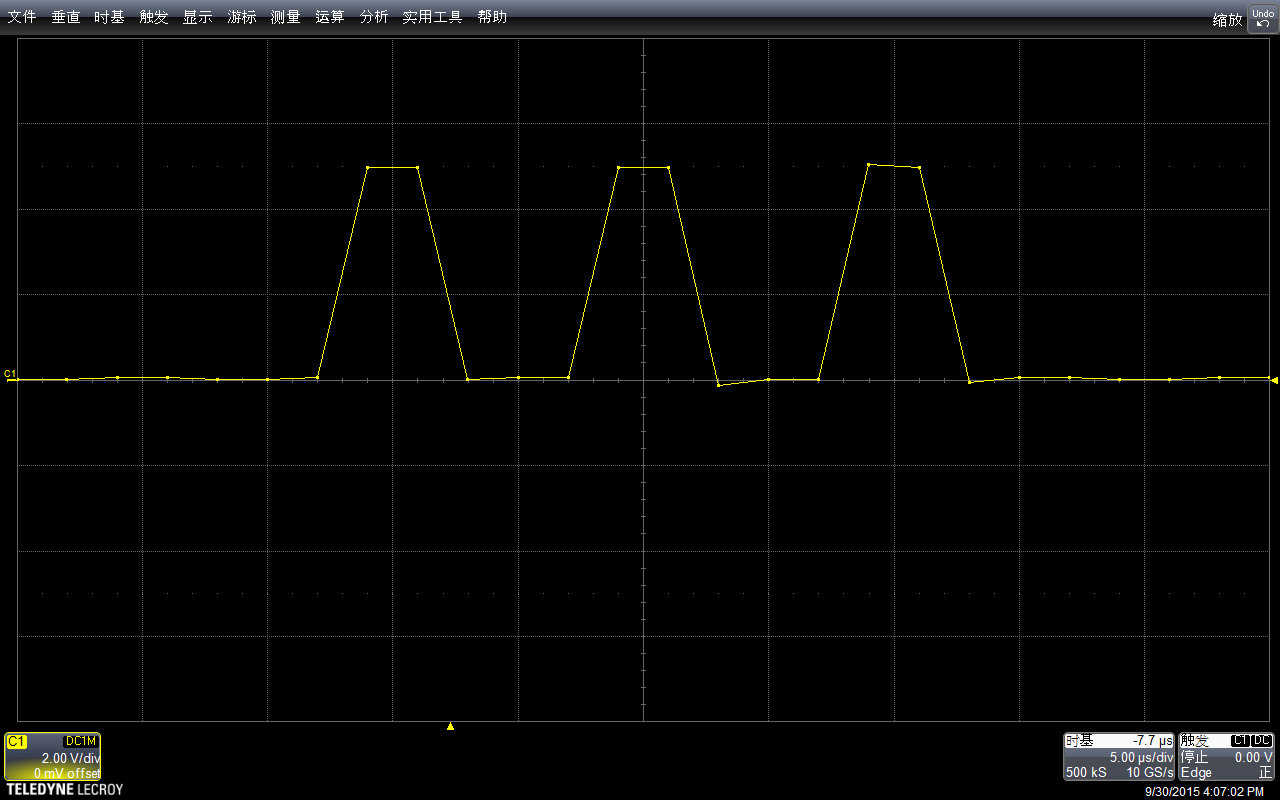
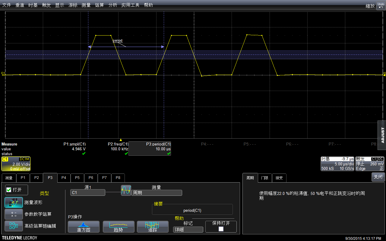
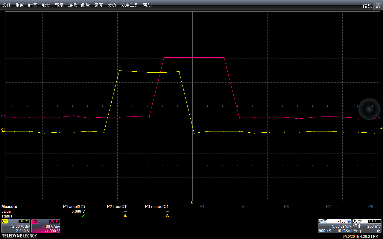
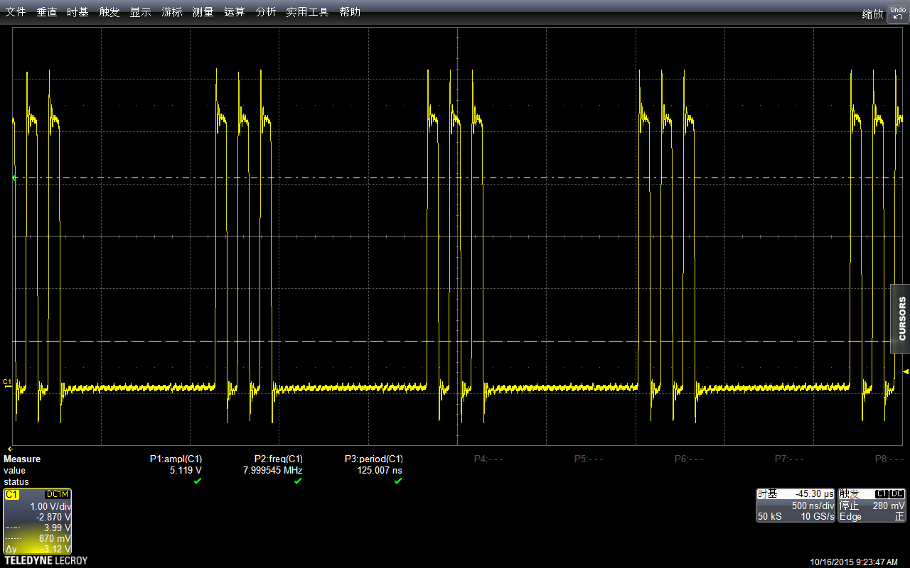
这个程序运行之后的波形如下
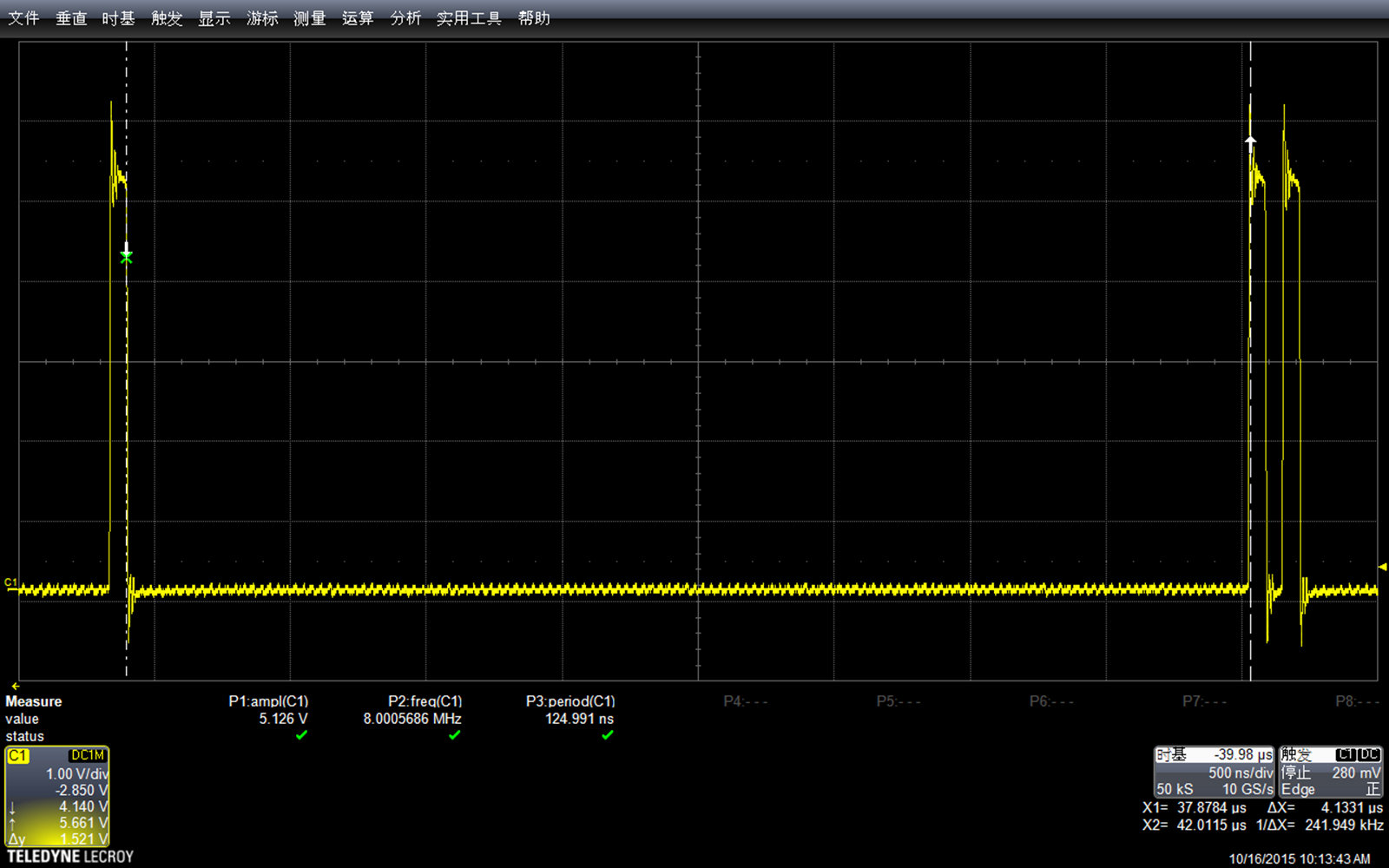
可以看到中间的延时差不多有4.1331us(我用游标对齐,右下角显示x=4.1331). 让然这个值中还包括了一个拉GPIO的指令周期,大约会有 62.1ns的影响。此外,如果要求特别精确,在使用时还要考虑周期性中断的影响。这里就不说了…….
下面我们继续实验,尝试找到循环次数和实际delay时间的关系(因为涉及到编译器优化, long int的计算和判断,直接尝试计算机器周期不可行)。
首先尝试zdelay<8,测量结果是3.7013us

根据上述值结合循环简单猜测一下,对于这个循环体,固定部分耗时0.2469us (比如给变量赋初始值),循环部分每次耗时0.4318us
就是 T= 0.2469 + n *0.4318
根据这个计算循环zdelay<5应该是 2.4059us测量结果是2.3722us
加入我们打算delay 100us 根据上述公式应该循环 231次
代码:
const int PinA =  13;
void setup() {
  pinMode(PinA, OUTPUT);
  digitalWrite(PinA,LOW);
}

void loop() {
  PORTB = B100000; //digitalWrite(PinA,HIGH);
  PORTB = B000000; //digitalWrite(PinA,LOW);

  for (long zdelay=0;zdelay<231; zdelay++) {
    __asm__("nop\n\t");
  }

  PORTB = B100000; //digitalWrite(PinA,HIGH);
  PORTB = B000000; //digitalWrite(PinA,LOW);
  PORTB = B100000; //digitalWrite(PinA,HIGH);
  PORTB = B000000;  //digitalWrite(PinA,LOW);
}
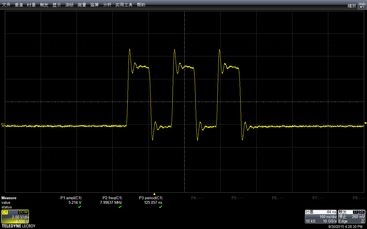
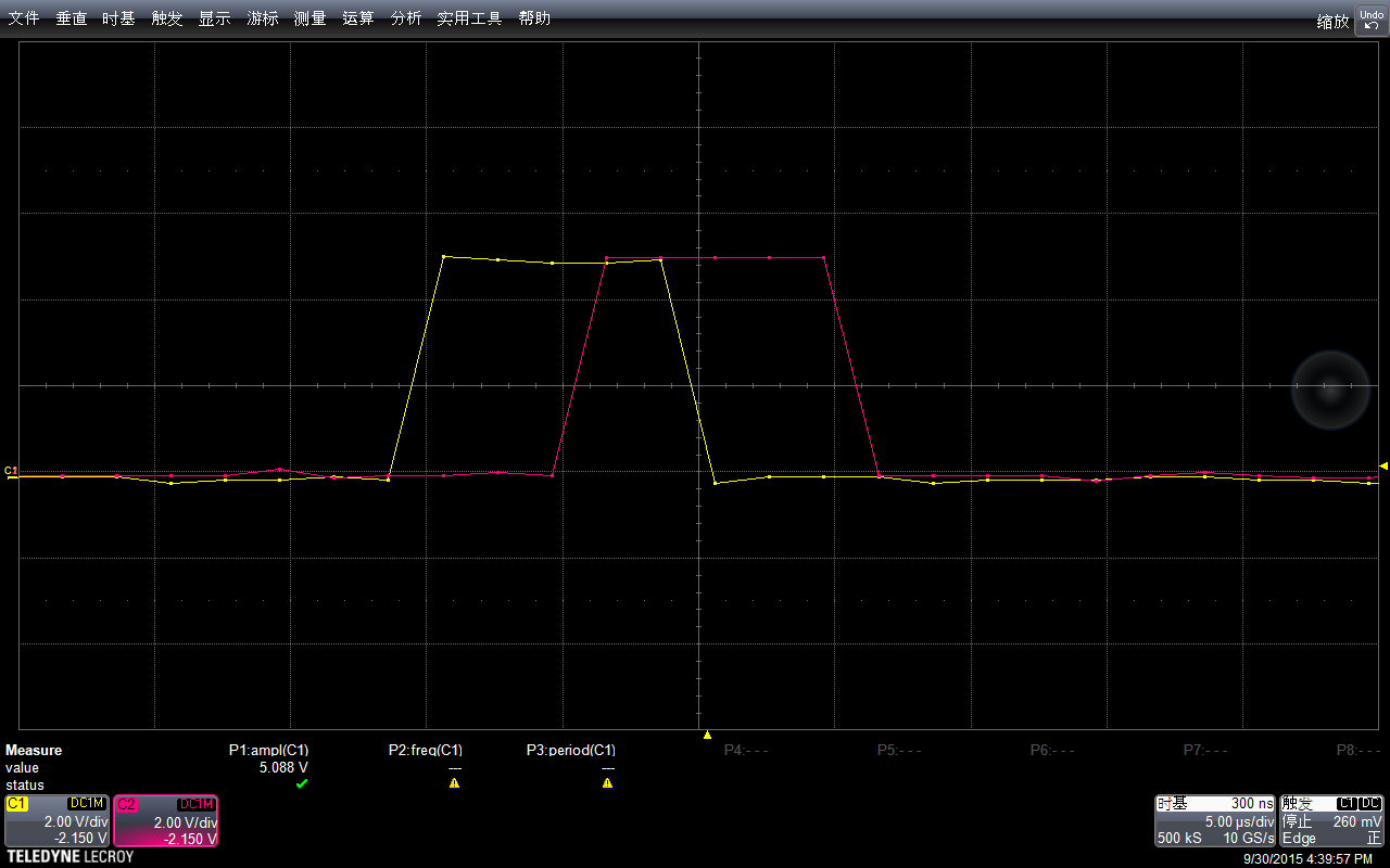
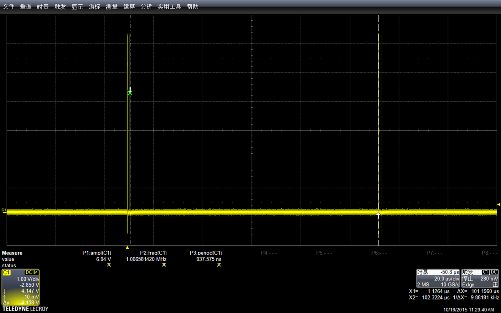
实际测试结果符合理论…….
最后,“极客工坊”的 sanyouhi 朋友指出,精确延时可以用写好的库来直接完成【参考1】
#define F_CPU 16000000
#include <util/delay.h>

void setup()
{
  DDRB = 0X20;
}

void loop()
{
PORTB = 0X20;
_delay_us(0.4);
PORTB = 0;
}
对应的头文件在 \arduino-1.6.3\hardware\tools\avr\avr\include\util\delay.h 有机会的时候再研究一下。
后记,比较有意思,如果我把代码写为下面的形式
const int PinA =  13;
void setup() {
  pinMode(PinA, OUTPUT);
  digitalWrite(PinA,LOW);
}

void loop() {
  PORTB = B100000; //digitalWrite(PinA,HIGH);
  for (long zdelay=0;zdelay<17; zdelay++) {
  }
  PORTB = B000000; //digitalWrite(PinA,LOW);
  PORTB = B100000; //digitalWrite(PinA,HIGH);
  PORTB = B000000; //digitalWrite(PinA,LOW);
  PORTB = B100000; //digitalWrite(PinA,HIGH);
  PORTB = B000000;  //digitalWrite(PinA,LOW);
}
中间delay 的周期和不写 for 循环是相同的,猜测原因是编译器的自动优化,当编译器发现空循环时会自动移除循环代码。
参考:
1.http://www.geek-workshop.com/thread-24982-1-1.html