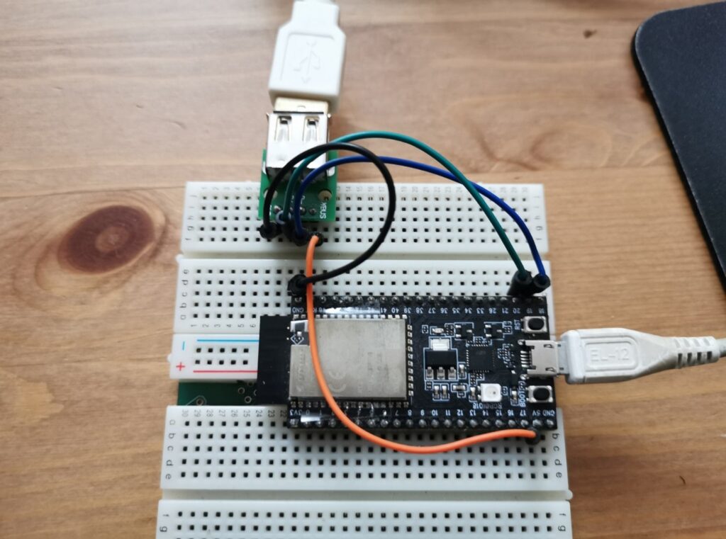
USB Host Shield 本身是支持USB Hub的,这样我们可以方便的一次性连接多个USB 设备。这次以USB 键盘为例进行测试。
USB Hub 的使用还是比较简单的,连接好之后,建议运行 USB_Host_Shield_Library_2.0\examples\hub_demo 这个示例代码进行测试,它会枚举当前USB Hub上的所有 USB 设备的描述符信息,通过这样的方法我们可以知道硬件是否能够工作正常。
前述代码测试通过后,我们就可以编写代码来获得按键信息了。
1. KBUnderHub.ino 代码中必须使用 USBHub ,之后,因为测试有3个键盘,所以要声明 kb1 到 kb3 三个设备
USB Usb;

USBHub Hub(&Usb);

KBSET kb1(&Usb);

KBSET kb2(&Usb);

KBSET kb3(&Usb);
2. KeyboardSets.h 代码中,申明一些我们需要的结构体如下:
// 当前支持的键盘数量
#define KBNUM 3

class KBSET : public HIDUniversal {
  public:
    KBSET(USB *p) : HIDUniversal(p) {};
    bool connected() {
      return HIDUniversal::isReady();
    };
    // 本次收到数据的键盘编号
    uint8_t  Current;
    // 存放第x个键盘是否有改变发生的标记
    bool     Changed[KBNUM];
    // 存放第x个键盘当前收到的缓冲区长度
    uint8_t  BufferSize[KBNUM];
    // 存放第x个键盘收到的缓冲区数据
    uint8_t  Buffer[KBNUM][64];
    // 存放第x个键盘的PID 和 VID
    uint16_t PID[KBNUM];
    uint16_t VID[KBNUM];
  private:
    void ParseHIDData(USBHID *hid, bool is_rpt_id, uint8_t len, uint8_t *buf); // Called by the HIDUniversal library
    uint8_t  BufferSizeOld[KBNUM];
    uint8_t  BufferOld[KBNUM][64];
    // 当前收到的键盘数据总数
    uint8_t  TotolKB;
    uint8_t OnInitSuccessful() { // Called by the HIDUniversal library on success
      KBSET::TotolKB = 0;
      for (uint8_t j = 0; j < KBNUM; j++) {
        for (uint8_t i = 0; i < 64; i++) {
          KBSET::BufferOld[j][i]=0xFF;
        }
      }
      return 0;
    };
};
3. KeyboardSets.cpp
#include "KeyboardSets.h"

void KBSET::ParseHIDData(USBHID *hid, bool is_rpt_id, uint8_t len, uint8_t *buf) {
  /*
    if (len && buf)  {
      Notify(PSTR("\r\n"), 0x80);
      for (uint8_t i = 0; i < len; i++) {
        D_PrintHex<uint8_t > (buf[i], 0x80);
        Notify(PSTR(" "), 0x80);
      }
    }
  */

  // 在 KBSET 中查找记录
  KBSET::Current = 0xFF;
  for (uint8_t i = 0; i < KBNUM; i++) {
    //
    if ((KBSET::PID[i] == HIDUniversal::PID) && (KBSET::VID[i] == HIDUniversal::VID)) {
      KBSET::Current = i;
    }
  }
  // 如果查找不到
  if (KBSET::Current == 0xFF) {
    KBSET::Current = KBSET::TotolKB;
    KBSET::PID[KBSET::Current] = HIDUniversal::PID;
    KBSET::VID[KBSET::Current] = HIDUniversal::VID;
    KBSET::BufferSize[KBSET::Current] = len;
    KBSET::TotolKB++;
  }

  // 检查本次数据和上次数据是否有差别
  if (memcmp(BufferOld[KBSET::Current], buf, len) == 0) {
    // 没有差别
    KBSET::Changed[KBSET::Current] = false;
  } else {
    memcpy(Buffer[KBSET::Current], buf, len);
    // 有差别
    KBSET::Changed[KBSET::Current] = true;
    memcpy(BufferOld[KBSET::Current], buf, len);
    Serial.print("VID:"); Serial.print(KBSET::VID[KBSET::Current],HEX);
    Serial.print(" PID:"); Serial.println(KBSET::PID[KBSET::Current],HEX);
    for (uint8_t i = 0; i < KBSET::BufferSize[KBSET::Current]; i++) {
      Serial.print((byte)(KBSET::Buffer[KBSET::Current][i]), HEX);
      Serial.print(" ");
    }
    Serial.println("");
  }
}
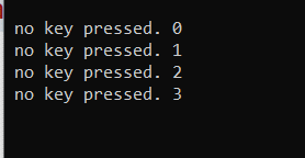
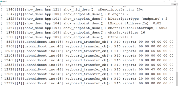
工作流程:当有按键事件发生时,库会调用 ParseHIDData() 这个函数,从设备获得的设备数据放在buf,产生数据的设备PID和 VID 在HIDUniversal::PID和HIDUniversal::VID中。之后,我们会在KBSET::PID VID数组中查找当前产生数据的设备是否已存在,如果没有话,将这个设备的PID和VID 加入数组中。之后再将改设备产生的数据存放到Buffer 中。之后,再判断新取得的数据和之前的BufferOld中保存的是否相同,如果相同就打印输出。
这样,我们就能分别获得三个设备产生的按键信息。
我是用了一个大键盘,一个小键盘和一个barcode scanner 作为测试设备,可以看到串口能够输出。
工作测试的视频:
https://www.bilibili.com/video/BV1nu411q7i7?share_source=copy_web
完整代码下载:
使用 MAX3421e 一个潜在的风险是:芯片本身价格高,比如前一段这个芯片价格炒到50以上,并且有假货。