微软的 MU 项目提供了一个 Shell 下的截图工具:PrintScreenLogger,具体的介绍可以在下面看到:
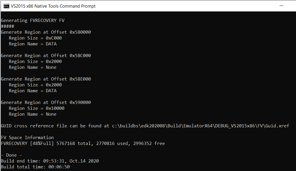
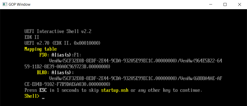
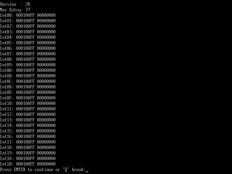
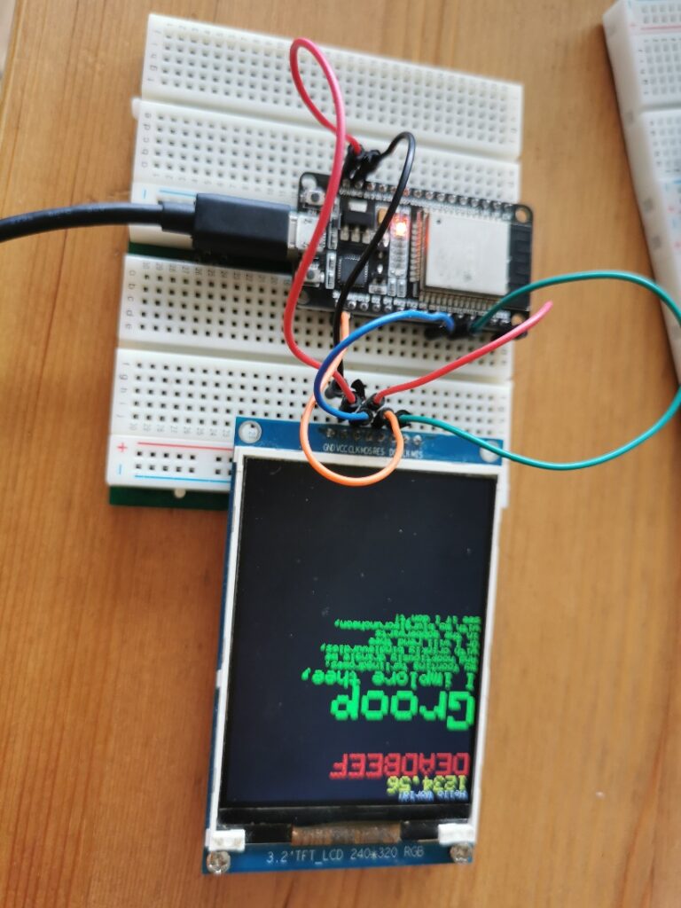
我尝试直接在 AppPkg 下编译了一下,可以通过编译。然后在实体机上进行了测试工作正常:
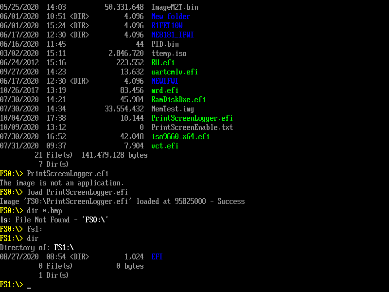
使用方法:
- 在你需要存放截图的盘上放置名为 PrintScreenEnable.txt 的文件(空文件即可),运行之后这个工具会将截图结果放置在存着这个文件的盘上;
- 使用 Load PrintScreenLogger.efi 加载(因为这个是一个 Driver);
- 截图快捷键是 ctrl + screen print ;
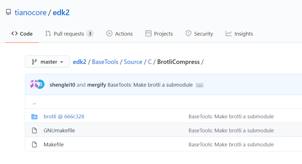
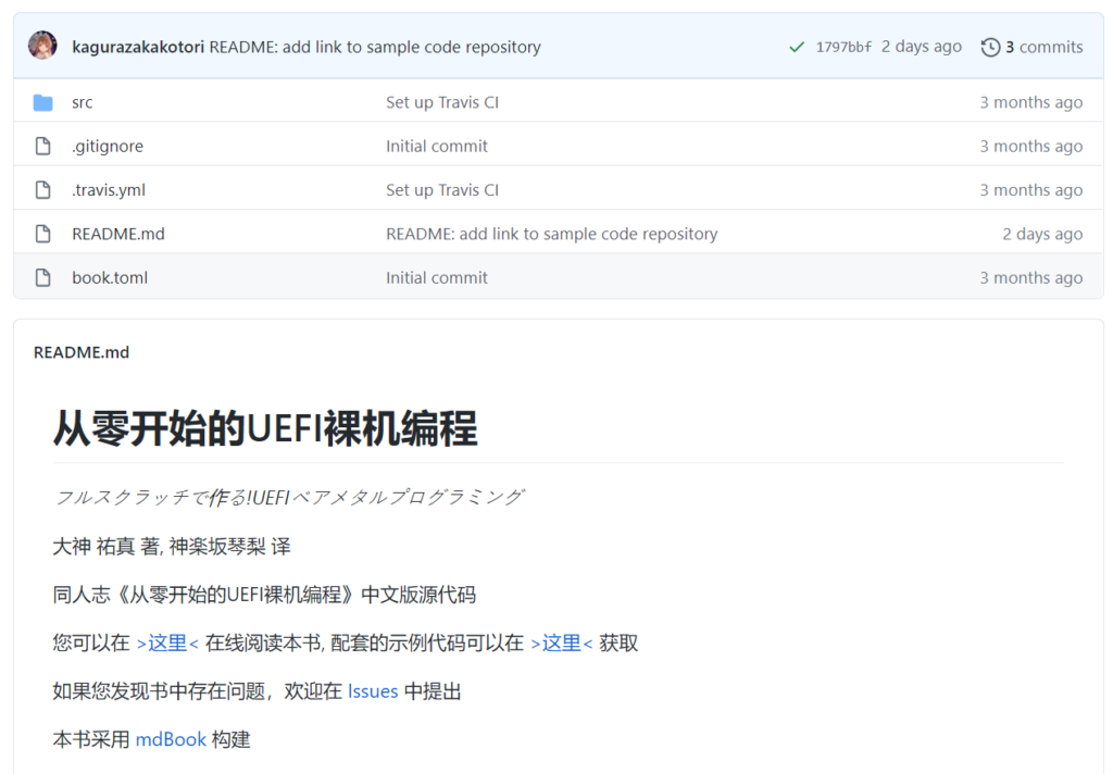
源代码来自 https://github.com/microsoft/mu_plus/tree/release/202005/MsGraphicsPkg/PrintScreenLogger:
/** @file
PrintScreenLogger.c

PrintScreen logger to capture UEFI menus into a BMP written to a USB key

Copyright (C) Microsoft Corporation. All rights reserved.
SPDX-License-Identifier: BSD-2-Clause-Patent

**/

#include "PrintScreenLogger.h"

typedef struct {
    EFI_KEY_DATA KeyData;
    EFI_HANDLE   NotifyHandle;
} PRINT_SCREEN_KEYS;
//
// PrtScreen comes in as an EFI_SYS_REQUEST shift state.
//
// Register two notifications, one for a RightCtrl-PrtScn and one for a LeftCtrl-PrtScn
//
STATIC PRINT_SCREEN_KEYS  gPrtScnKeys[] = {
    {
        {
            {0,0},
            {EFI_SHIFT_STATE_VALID | EFI_LEFT_CONTROL_PRESSED  | EFI_SYS_REQ_PRESSED, 0}
        },
        NULL
    },
    {
        {
            {0,0},
            {EFI_SHIFT_STATE_VALID | EFI_RIGHT_CONTROL_PRESSED | EFI_SYS_REQ_PRESSED, 0}
        },
        NULL
    }
};

#define NUMBER_KEY_NOTIFIES (sizeof(gPrtScnKeys)/sizeof(PRINT_SCREEN_KEYS))

// Global variables.
//
STATIC EFI_SIMPLE_TEXT_INPUT_EX_PROTOCOL *gTxtInEx    = NULL;
STATIC EFI_EVENT                          gTimerEvent = NULL;

/**

  Scan USB Drives looking for a file named PrintScreenEnable.txt.  The presence
  of this file indicates it is OK to write print screen files to this drive.

  @param    Fs_Handle       Handle to the opened volume.

  @retval   EFI_SUCCESS     The FS volume was opened successfully.
  @retval   Others          The operation failed.

**/
EFI_STATUS
FindUsbDriveForPrintScreen (
  OUT EFI_FILE_PROTOCOL  **VolumeHandle
  )
{
    EFI_FILE_PROTOCOL               *FileHandle;
    EFI_FILE_PROTOCOL               *VolHandle;
    EFI_HANDLE                      *HandleBuffer;
    UINTN                            Index;
    UINTN                            NumHandles;
    EFI_STATUS                       Status;
    EFI_STATUS                       Status2;
    EFI_DEVICE_PATH_PROTOCOL        *BlkIoDevicePath;
    EFI_DEVICE_PATH_PROTOCOL        *UsbDevicePath;
    EFI_SIMPLE_FILE_SYSTEM_PROTOCOL *SfProtocol;
    EFI_HANDLE                       Handle;

    NumHandles = 0;
    HandleBuffer = NULL;
    SfProtocol = NULL;

    //
    // Locate all handles that are using the SFS protocol.
    //
    Status = gBS->LocateHandleBuffer(ByProtocol,
                                     &gEfiSimpleFileSystemProtocolGuid,
                                     NULL,
                                     &NumHandles,
                                     &HandleBuffer);

    if (EFI_ERROR(Status) != FALSE) {
        DEBUG((DEBUG_ERROR, "%a: failed to locate any handles using the Simple FS protocol (%r)\n", __FUNCTION__, Status));
        goto CleanUp;
    }

    //
    // Search the handles to find one that has has a USB node in the device path.
    //
    for (Index = 0; (Index < NumHandles); Index += 1) {
        //
        // Insure this device is on a USB controller
        //
        UsbDevicePath = DevicePathFromHandle(HandleBuffer[Index]);
        if (UsbDevicePath == NULL) {
            continue;
        }
        Status = gBS->LocateDevicePath (&gEfiUsbIoProtocolGuid,
                                        &UsbDevicePath,
                                        &Handle);
        if (EFI_ERROR(Status)) {
            // Device is not USB;
            continue;
        }

        //
        // Check if this is a block IO device path.
        //
        BlkIoDevicePath = DevicePathFromHandle(HandleBuffer[Index]);
        if (BlkIoDevicePath == NULL) {
            continue;
        }
        Status = gBS->LocateDevicePath(&gEfiBlockIoProtocolGuid,
                                       &BlkIoDevicePath,
                                       &Handle);
        if (EFI_ERROR(Status)) {
            // Device is not BlockIo;
            continue;
        }

        Status = gBS->HandleProtocol(HandleBuffer[Index],
                                     &gEfiSimpleFileSystemProtocolGuid,
                                     (VOID**)&SfProtocol);

        if (EFI_ERROR(Status)) {
            DEBUG((DEBUG_ERROR, "%a: Failed to locate Simple FS protocol. %r\n", __FUNCTION__, Status));
            continue;
        }

        //
        // Open the volume/partition.
        //
        Status = SfProtocol->OpenVolume(SfProtocol, &VolHandle);
        if (EFI_ERROR(Status) != FALSE) {
            DEBUG((DEBUG_ERROR,"%a: Unable to open SimpleFileSystem. Code = %r\n", __FUNCTION__, Status));
            continue;
        }

        //
        // Insure the PrinteScreenEnable.txt file is present
        //
        Status = VolHandle->Open (VolHandle, &FileHandle, PRINT_SCREEN_ENABLE_FILENAME, EFI_FILE_MODE_READ, 0);
        if (EFI_ERROR(Status)) {
            DEBUG((DEBUG_INFO,"%a: Print Screen not supported to this device. Code = %r\n", __FUNCTION__, Status));
            Status2 = VolHandle->Close (VolHandle);
            if (EFI_ERROR(Status2)) {
                DEBUG((DEBUG_ERROR,"%a: Error closing Vol Handle. Code = %r\n", __FUNCTION__, Status2));
            }
            continue;
        }

        FileHandle->Close (FileHandle);
        *VolumeHandle = VolHandle;
        Status = EFI_SUCCESS;
        break;
    }

CleanUp:
    if (HandleBuffer != NULL) {
        FreePool(HandleBuffer);
    }

    return Status;
}

/**
  Convert a Gop 32 bits per pixel video frame buffer to a
  24 bits per pixel *.BMP graphics image

  @param  BmpFileName   Name of file to create
  @param  Gop           GRAPHICS_OUTPUT_PROTOCOL
  @param  BltBuffer     Buffer containing GOP version of BmpImage.

  @retval EFI_SUCCESS           GopBlt and GopBltSize are returned.
  @retval EFI_UNSUPPORTED       BmpImage is not a valid *.BMP image
  @retval EFI_BUFFER_TOO_SMALL  The passed in GopBlt buffer is not big enough.
                                GopBltSize will contain the required size.
  @retval EFI_OUT_OF_RESOURCES  No enough buffer to allocate.

**/
EFI_STATUS
WriteBmpToFile (
  IN EFI_FILE_PROTOCOL             *FileHandle
) {

    EFI_STATUS                     Status;
    BMP_IMAGE_HEADER              *BmpHeader;
    UINTN                          DataSizePerLine;
    UINTN                          BmpBufferSize;
    UINT8                         *Image;
    EFI_GRAPHICS_OUTPUT_BLT_PIXEL *Blt;
    EFI_GRAPHICS_OUTPUT_BLT_PIXEL *BltBuffer;
    UINT32                         Height;
    UINT32                         Width;
    UINT64                         WriteSize;

    EFI_GRAPHICS_OUTPUT_PROTOCOL   *Gop;

#define BMP_BITS_PER_PIXEL  24

    BmpHeader = NULL;
    BltBuffer = NULL;

    Status = gBS->LocateProtocol (&gEfiGraphicsOutputProtocolGuid,
                                  NULL,
                                  (VOID **)&Gop
                                 );
    if (EFI_ERROR(Status)) {
        DEBUG((DEBUG_ERROR, "Unable to locate Gop protocol\n"));
        return Status;
    }

    if ((Gop->Mode->Info->PixelFormat != PixelRedGreenBlueReserved8BitPerColor) &&
        (Gop->Mode->Info->PixelFormat != PixelBlueGreenRedReserved8BitPerColor)) {
        DEBUG((DEBUG_ERROR, "%a: Unsupported video mode\n", __FUNCTION__));
        return EFI_UNSUPPORTED;
    }

    BltBuffer = (EFI_GRAPHICS_OUTPUT_BLT_PIXEL *)  AllocatePool (Gop->Mode->FrameBufferSize);
    if (NULL == BltBuffer) {
        return EFI_OUT_OF_RESOURCES;
    }

    Height = Gop->Mode->Info->VerticalResolution;
    Width = Gop->Mode->Info->HorizontalResolution;

    Status = Gop->Blt (Gop,
                       BltBuffer,
                       EfiBltVideoToBltBuffer,
                       0,
                       0,
                       0,
                       0,
                       Width,
                       Height,
                       0
                      );
    if (EFI_ERROR(Status)) {
        DEBUG((DEBUG_ERROR, "Unable to BLt video to buffer, code=%r\n",Status));
        goto ErrorExit;
    }

    DataSizePerLine = ((Gop->Mode->Info->HorizontalResolution * BMP_BITS_PER_PIXEL + 31) >> 3) & (~0x3);
    BmpBufferSize = MultU64x32 (DataSizePerLine, Gop->Mode->Info->VerticalResolution) + sizeof(BMP_IMAGE_HEADER) + ((sizeof(BMP_IMAGE_HEADER) + 3) & ~0x03);

    if (BmpBufferSize > (UINT32) ~0) {
        Status = EFI_INVALID_PARAMETER;
        goto ErrorExit;
    }

    BmpHeader = AllocateZeroPool (BmpBufferSize); // Insure unfilled area is zeroed
    if (NULL == BmpHeader) {
        Status = EFI_OUT_OF_RESOURCES;
        goto ErrorExit;
    }

    Status = EFI_SUCCESS;

    BmpHeader->CharB = 'B';           // Header flag
    BmpHeader->CharM = 'M';
    BmpHeader->Size = (UINT32) BmpBufferSize;
    BmpHeader->Reserved[0] = 0;
    BmpHeader->Reserved[1] = 0;
    BmpHeader->ImageOffset = (sizeof(BMP_IMAGE_HEADER) + 3) & ~0x03;  // Start first row on 4 byte boundary
    BmpHeader->HeaderSize = sizeof (BMP_IMAGE_HEADER) - OFFSET_OF(BMP_IMAGE_HEADER, HeaderSize);
    BmpHeader->PixelWidth = Width;
    BmpHeader->PixelHeight = Height;
    BmpHeader->Planes = 1;
    BmpHeader->BitPerPixel = 24;
    BmpHeader->CompressionType = 0;   // Not Compressed
    BmpHeader->ImageSize = 0;
    BmpHeader->XPixelsPerMeter = 11000;  // Approximately 300 dpi
    BmpHeader->YPixelsPerMeter = 11000;
    BmpHeader->NumberOfColors = 0;
    BmpHeader->ImportantColors = 0;

    Image = ((UINT8 *) BmpHeader) + BmpHeader->ImageOffset;

    for (Height = 0; Height < BmpHeader->PixelHeight; Height++) {
        Blt = &BltBuffer[(BmpHeader->PixelHeight - Height - 1) * BmpHeader->PixelWidth];
        for (Width = 0; Width < BmpHeader->PixelWidth; Width++, Blt++) {
            if (Gop->Mode->Info->PixelFormat == PixelRedGreenBlueReserved8BitPerColor) {
                *Image++ = Blt->Red;
                *Image++ = Blt->Green;
                *Image++ = Blt->Blue;
            } else {    // PixelBlueGreenRedReserved8BitPerColor
                *Image++ = Blt->Blue;
                *Image++ = Blt->Green;
                *Image++ = Blt->Red;
            }
        }
        Image = (UINT8 *)(  ((UINT64)Image + 3) & ~0x03);  // Start next row on 4 byte boundary.
    }

    WriteSize = BmpBufferSize;
    Status = FileHandle->Write (FileHandle, &WriteSize, BmpHeader);
    if (EFI_ERROR(Status)) {
        DEBUG((DEBUG_ERROR, "Error writing Bmp file. Code=%r\n", Status));
    }
    if (WriteSize != BmpBufferSize) {
        DEBUG((DEBUG_ERROR, "Wrong number of bytes written.  S/B=%ld, Actual=%ld\n", BmpBufferSize, WriteSize));
        Status = EFI_BAD_BUFFER_SIZE;
    }

ErrorExit:
    if (BltBuffer != NULL) {
        FreePool (BltBuffer);
    }

    if (BmpHeader != NULL) {
        FreePool (BmpHeader );
    }

    return Status;
}

/**
  Handler for hot key notification

  @param KeyData         A pointer to a buffer that is filled in with the keystroke
                         information for the key that was pressed.

  @retval  EFI_SUCCESS   Always - Return code is not used by SimpleText providers.

**/
EFI_STATUS
EFIAPI
PrintScreenCallback (
  IN EFI_KEY_DATA     *KeyData
)
{
    EFI_FILE_PROTOCOL *FileHandle;
    UINTN              Index;
    CHAR16             PrtScrnFileName[] = L"PrtScreen####.bmp";
    EFI_STATUS         Status;
    EFI_STATUS         Status2;
    EFI_FILE_PROTOCOL *VolumeHandle;

    // We only register two keys - LeftCtrl-PrtScn and RightCtrl-PrtScn.
    // Assume print screen function if this function is called.
    DEBUG((DEBUG_INFO,"%a: Starting PrintScreen capture. Sc=%x, Uc=%x, Sh=%x, Ts=%x\n",
        __FUNCTION__,
        KeyData->Key.ScanCode,
        KeyData->Key.UnicodeChar,
        KeyData->KeyState.KeyShiftState,
        KeyData->KeyState.KeyToggleState));

    Status = gBS->CheckEvent (gTimerEvent);

    if (Status == EFI_NOT_READY) {
        DEBUG((DEBUG_INFO,"Print Screen request ignored\n"));
        return EFI_SUCCESS;
    }

    //
    // 1. Find a suitable USB drive - one that has PrintScreenEnable.txt on it.
    //
    Status = FindUsbDriveForPrintScreen(&VolumeHandle);

    if (!EFI_ERROR(Status)) {
        //
        // 2. Find the first value of PrtScreen#### that is available
        //
        Index = 0;

        do {
            Index++;
            if (Index > MAX_PRINT_SCREEN_FILES) {
                goto Exit;
            }

            UnicodeSPrint (PrtScrnFileName, sizeof (PrtScrnFileName), L"PrtScreen%04d.bmp", Index);
            Status = VolumeHandle->Open (VolumeHandle, &FileHandle, PrtScrnFileName, EFI_FILE_MODE_READ, 0);
            if (!EFI_ERROR(Status)) {
                if (Index % PRINT_SCREEN_DEBUG_WARNING == 0) {
                    DEBUG((DEBUG_INFO,"%a: File %s exists.  Trying again\n", __FUNCTION__, PrtScrnFileName));
                }
                Status2 = FileHandle->Close (FileHandle);
                if (EFI_ERROR(Status2)) {
                    DEBUG((DEBUG_ERROR,"%a: Error closing File Handle. Code = %r\n", __FUNCTION__, Status2));
                }
                continue;
            }
            if (Status == EFI_NOT_FOUND) {
                break;
            }
        } while (TRUE);

        //
        // 3. Create the new file that will contain the bitmap
        //
        Status = VolumeHandle->Open (VolumeHandle, &FileHandle, PrtScrnFileName, EFI_FILE_MODE_READ | EFI_FILE_MODE_WRITE | EFI_FILE_MODE_CREATE, EFI_FILE_ARCHIVE);
        if (EFI_ERROR(Status)) {
            DEBUG((DEBUG_ERROR,"%a: Unable to create file %s. Code = %r\n", __FUNCTION__, PrtScrnFileName, Status));
            goto Exit;
        }

        //
        // 4. Write the contents of the display to the new file
        //
        Status = WriteBmpToFile (FileHandle);
        if (!EFI_ERROR(Status)) {
            DEBUG((DEBUG_INFO,"%a: Screen captured to file %s.\n", __FUNCTION__, PrtScrnFileName));
        }
        //
        // 4. Close the bitmap file
        //
        Status2 = FileHandle->Close (FileHandle);
        if (EFI_ERROR(Status2)) {
            DEBUG((DEBUG_ERROR,"%a: Error closing bit map file %s. Code = %r\n", __FUNCTION__, PrtScrnFileName, Status2));
        }
Exit:
        //
        // 5. Close the USB volume
        //
        Status2 = VolumeHandle->Close (VolumeHandle);
        if (EFI_ERROR(Status2)) {
            DEBUG((DEBUG_ERROR,"%a: Error closing Vol Handle. Code = %r\n", __FUNCTION__, Status2));
        }
    }

    // Ignore future PrtScn requests for some period.  This is due to the make
    // and break of PrtScn being identical, and it takes a few seconds to complete
    // a single screen capture.
    Status = gBS->SetTimer (gTimerEvent, TimerRelative, PRINT_SCREEN_DELAY);

    return EFI_SUCCESS;
}

/**
  Unregister TxtIn callbacks and end the timer

**/
VOID
UnRegisterNotifications (
    VOID
    ) {
    INTN       i;
    EFI_STATUS Status;

    for (i = 0; i < NUMBER_KEY_NOTIFIES; i++) {
        if (gPrtScnKeys[i].NotifyHandle != NULL) {
            Status = gTxtInEx->UnregisterKeyNotify (gTxtInEx,  gPrtScnKeys[i].NotifyHandle);
            if (EFI_ERROR(Status)) {
                DEBUG((DEBUG_ERROR, "%a: Unable to uninstall TxtIn Notify. Code = %r\n", __FUNCTION__, Status));
            }
        }
    }

    if (gTimerEvent != NULL) {
        gBS->SetTimer (gTimerEvent, TimerCancel, 0);
        gBS->CloseEvent (gTimerEvent);

    }
}

/**

  Callback to cleanup the driver on unload.

  @param    Event           Not Used.
  @param    Context         Not Used.

  @retval   None

**/
EFI_STATUS
EFIAPI
PrintScreenLoggerUnload (
  IN  EFI_HANDLE   ImageHandle
  )
{

    DEBUG((DEBUG_INFO, "%a: unloading...\n", __FUNCTION__));

    UnRegisterNotifications ();

    return EFI_SUCCESS;
}

/**
  Main entry point for this driver.

  @param    ImageHandle     Image handle of this driver.
  @param    SystemTable     Pointer to the system table.

  @retval   EFI_STATUS      Always returns EFI_SUCCESS.

**/
EFI_STATUS
EFIAPI
PrintScreenLoggerEntry (
  IN EFI_HANDLE           ImageHandle,
  IN EFI_SYSTEM_TABLE     *SystemTable
  )
{
    EFI_STATUS      Status = EFI_NOT_FOUND;
    INTN            i;

    DEBUG((DEBUG_LOAD, "%a: enter...\n", __FUNCTION__));

    //
    // 1. Get access to ConSplitter's TextInputEx protocol
    //
    if (gST->ConsoleInHandle != NULL) {
        Status = gBS->OpenProtocol (
                        gST->ConsoleInHandle,
                        &gEfiSimpleTextInputExProtocolGuid,
                        (VOID **) &gTxtInEx,
                        ImageHandle,
                        NULL,
                        EFI_OPEN_PROTOCOL_BY_HANDLE_PROTOCOL);
    }

    if (EFI_ERROR(Status)) {
        DEBUG((DEBUG_ERROR, "%a: Unable to access TextInputEx protocol. Code = %r\n", __FUNCTION__, Status));
    }  else {

        //
        // 2.  Register for PrtScn callbacks
        //
        for (i = 0; i < NUMBER_KEY_NOTIFIES; i++) {
             Status = gTxtInEx->RegisterKeyNotify (
                          gTxtInEx,
                          &gPrtScnKeys[i].KeyData,
                          PrintScreenCallback,
                          &gPrtScnKeys[i].NotifyHandle);
            if (EFI_ERROR (Status)) {
                 DEBUG ((DEBUG_ERROR, "%a: Error registering key %d. Code = %r\n", __FUNCTION__, i, Status));
                 break;
            }
        }

        if (!EFI_ERROR(Status)) {
            //
            // 3. Create the PrtScn hold off timer
            //
            Status = gBS->CreateEvent(
                                EVT_TIMER,
                                0,
                                NULL,
                                NULL,
                                &gTimerEvent);
            if (!EFI_ERROR(Status)) {
                //
                // 4. Place event into the signaled state indicating PrtScn is active.
                //
                Status = gBS->SignalEvent (gTimerEvent);
            }
        }

        if (!EFI_ERROR(Status)) {
            DEBUG((DEBUG_INFO, "%a: exit. Ready for Ctl-PrtScn operation\n", __FUNCTION__));
        } else {
            UnRegisterNotifications ();
            DEBUG((DEBUG_ERROR, "%a: exit with errors. Ctl-PrtScn not operational. Code=%r\n", __FUNCTION__, Status));
        }
    }

    return EFI_SUCCESS;
}
完整代码下载:
编译后的 X64 EFI 下载:

