上一篇介绍了 RSA 的基本原理和例子,这里介绍一下 UEFI Shell 下的实现。正规的实现方法需要使用
CyptoPkg 加
OpenSSL 源代码,但是我在查看
CyptoPkg 的时候发现目前只有 RSA 做身份认证的部分,加之 OpenSSL 使用起来很繁琐。因此,这里通过RSAEuro 库【参考1】来实现。
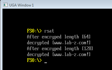
根据库提供的文档,编写测试代码。首先是测试通过给定的 RSA Private Key 加密,然后 Public Key 解密。再测试随机生成 Private Key然后 Public Key进行解密。
#include  <Uefi.h>
#include  <Library/UefiLib.h>
#include  <Library/ShellCEntryLib.h>
#include  <Library/BaseMemoryLib.h>
#include  <stdio.h>
#include  <string.h>
#include  <stdlib.h>

#include "rsaeuro/rsaeuro.h"
#include "rsaeuro/rsa.h"

static R_RSA_PUBLIC_KEY PUBLIC_KEY1 = {
	512,
	{0x00, 0x00, 0x00, 0x00, 0x00, 0x00, 0x00, 0x00, 0x00, 0x00, 0x00, 0x00,
	 0x00, 0x00, 0x00, 0x00, 0x00, 0x00, 0x00, 0x00, 0x00, 0x00, 0x00, 0x00,
	 0x00, 0x00, 0x00, 0x00, 0x00, 0x00, 0x00, 0x00, 0x00, 0x00, 0x00, 0x00,
	 0x00, 0x00, 0x00, 0x00, 0x00, 0x00, 0x00, 0x00, 0x00, 0x00, 0x00, 0x00,
	 0x00, 0x00, 0x00, 0x00, 0x00, 0x00, 0x00, 0x00, 0x00, 0x00, 0x00, 0x00,
	 0x00, 0x00, 0x00, 0x00, 0xc0, 0x76, 0x47, 0x97, 0xb8, 0xbe, 0xc8, 0x97,
	 0x2a, 0x0e, 0xd8, 0xc9, 0x0a, 0x8c, 0x33, 0x4d, 0xd0, 0x49, 0xad, 0xd0,
	 0x22, 0x2c, 0x09, 0xd2, 0x0b, 0xe0, 0xa7, 0x9e, 0x33, 0x89, 0x10, 0xbc,
	 0xae, 0x42, 0x20, 0x60, 0x90, 0x6a, 0xe0, 0x22, 0x1d, 0xe3, 0xf3, 0xfc,
	 0x74, 0x7c, 0xcf, 0x98, 0xae, 0xcc, 0x85, 0xd6, 0xed, 0xc5, 0x2d, 0x93,
	 0xd5, 0xb7, 0x39, 0x67, 0x76, 0x16, 0x05, 0x25},
	{0x00, 0x00, 0x00, 0x00, 0x00, 0x00, 0x00, 0x00, 0x00, 0x00, 0x00, 0x00,
	 0x00, 0x00, 0x00, 0x00, 0x00, 0x00, 0x00, 0x00, 0x00, 0x00, 0x00, 0x00,
	 0x00, 0x00, 0x00, 0x00, 0x00, 0x00, 0x00, 0x00, 0x00, 0x00, 0x00, 0x00,
	 0x00, 0x00, 0x00, 0x00, 0x00, 0x00, 0x00, 0x00, 0x00, 0x00, 0x00, 0x00,
	 0x00, 0x00, 0x00, 0x00, 0x00, 0x00, 0x00, 0x00, 0x00, 0x00, 0x00, 0x00,
	 0x00, 0x00, 0x00, 0x00, 0x00, 0x00, 0x00, 0x00, 0x00, 0x00, 0x00, 0x00,
	 0x00, 0x00, 0x00, 0x00, 0x00, 0x00, 0x00, 0x00, 0x00, 0x00, 0x00, 0x00,
	 0x00, 0x00, 0x00, 0x00, 0x00, 0x00, 0x00, 0x00, 0x00, 0x00, 0x00, 0x00,
	 0x00, 0x00, 0x00, 0x00, 0x00, 0x00, 0x00, 0x00, 0x00, 0x00, 0x00, 0x00,
	 0x00, 0x00, 0x00, 0x00, 0x00, 0x00, 0x00, 0x00, 0x00, 0x00, 0x00, 0x00,
	 0x00, 0x00, 0x00, 0x00, 0x00, 0x01, 0x00, 0x01}
};

static R_RSA_PRIVATE_KEY PRIVATE_KEY1 = {
	512,
	{0x00, 0x00, 0x00, 0x00, 0x00, 0x00, 0x00, 0x00, 0x00, 0x00, 0x00, 0x00,
	 0x00, 0x00, 0x00, 0x00, 0x00, 0x00, 0x00, 0x00, 0x00, 0x00, 0x00, 0x00,
	 0x00, 0x00, 0x00, 0x00, 0x00, 0x00, 0x00, 0x00, 0x00, 0x00, 0x00, 0x00,
	 0x00, 0x00, 0x00, 0x00, 0x00, 0x00, 0x00, 0x00, 0x00, 0x00, 0x00, 0x00,
	 0x00, 0x00, 0x00, 0x00, 0x00, 0x00, 0x00, 0x00, 0x00, 0x00, 0x00, 0x00,
	 0x00, 0x00, 0x00, 0x00, 0xc0, 0x76, 0x47, 0x97, 0xb8, 0xbe, 0xc8, 0x97,
	 0x2a, 0x0e, 0xd8, 0xc9, 0x0a, 0x8c, 0x33, 0x4d, 0xd0, 0x49, 0xad, 0xd0,
	 0x22, 0x2c, 0x09, 0xd2, 0x0b, 0xe0, 0xa7, 0x9e, 0x33, 0x89, 0x10, 0xbc,
   0xae, 0x42, 0x20, 0x60, 0x90, 0x6a, 0xe0, 0x22, 0x1d, 0xe3, 0xf3, 0xfc,
	 0x74, 0x7c, 0xcf, 0x98, 0xae, 0xcc, 0x85, 0xd6, 0xed, 0xc5, 0x2d, 0x93,
   0xd5, 0xb7, 0x39, 0x67, 0x76, 0x16, 0x05, 0x25},
  {0x00, 0x00, 0x00, 0x00, 0x00, 0x00, 0x00, 0x00, 0x00, 0x00, 0x00, 0x00,
	 0x00, 0x00, 0x00, 0x00, 0x00, 0x00, 0x00, 0x00, 0x00, 0x00, 0x00, 0x00,
	 0x00, 0x00, 0x00, 0x00, 0x00, 0x00, 0x00, 0x00, 0x00, 0x00, 0x00, 0x00,
   0x00, 0x00, 0x00, 0x00, 0x00, 0x00, 0x00, 0x00, 0x00, 0x00, 0x00, 0x00,
   0x00, 0x00, 0x00, 0x00, 0x00, 0x00, 0x00, 0x00, 0x00, 0x00, 0x00, 0x00,
	 0x00, 0x00, 0x00, 0x00, 0x00, 0x00, 0x00, 0x00, 0x00, 0x00, 0x00, 0x00,
	 0x00, 0x00, 0x00, 0x00, 0x00, 0x00, 0x00, 0x00, 0x00, 0x00, 0x00, 0x00,
	 0x00, 0x00, 0x00, 0x00, 0x00, 0x00, 0x00, 0x00, 0x00, 0x00, 0x00, 0x00,
   0x00, 0x00, 0x00, 0x00, 0x00, 0x00, 0x00, 0x00, 0x00, 0x00, 0x00, 0x00,
   0x00, 0x00, 0x00, 0x00, 0x00, 0x00, 0x00, 0x00, 0x00, 0x00, 0x00, 0x00,
   0x00, 0x00, 0x00, 0x00, 0x00, 0x01, 0x00, 0x01},
  {0x00, 0x00, 0x00, 0x00, 0x00, 0x00, 0x00, 0x00, 0x00, 0x00, 0x00, 0x00,
   0x00, 0x00, 0x00, 0x00, 0x00, 0x00, 0x00, 0x00, 0x00, 0x00, 0x00, 0x00,
   0x00, 0x00, 0x00, 0x00, 0x00, 0x00, 0x00, 0x00, 0x00, 0x00, 0x00, 0x00,
   0x00, 0x00, 0x00, 0x00, 0x00, 0x00, 0x00, 0x00, 0x00, 0x00, 0x00, 0x00,
   0x00, 0x00, 0x00, 0x00, 0x00, 0x00, 0x00, 0x00, 0x00, 0x00, 0x00, 0x00,
	 0x00, 0x00, 0x00, 0x00, 0x1a, 0xe3, 0x6b, 0x75, 0x22, 0xf6, 0x64, 0x87,
	 0xd9, 0xf4, 0x61, 0x0d, 0x15, 0x50, 0x29, 0x0a, 0xc2, 0x02, 0xc9, 0x29,
   0xbe, 0xdc, 0x70, 0x32, 0xcc, 0x3e, 0x02, 0xac, 0xf3, 0x7e, 0x3e, 0xbc,
	 0x1f, 0x86, 0x6e, 0xe7, 0xef, 0x7a, 0x08, 0x68, 0xd2, 0x3a, 0xe2, 0xb1,
   0x84, 0xc1, 0xab, 0xd6, 0xd4, 0xdb, 0x8e, 0xa9, 0xbe, 0xc0, 0x46, 0xbd,
	 0x82, 0x80, 0x37, 0x27, 0xf2, 0x88, 0x87, 0x01},
	{{0x00, 0x00, 0x00, 0x00, 0x00, 0x00, 0x00, 0x00, 0x00, 0x00, 0x00, 0x00,
		0x00, 0x00, 0x00, 0x00, 0x00, 0x00, 0x00, 0x00, 0x00, 0x00, 0x00, 0x00,
		0x00, 0x00, 0x00, 0x00, 0x00, 0x00, 0x00, 0x00, 0xdf, 0x02, 0xb6, 0x15,
		0xfe, 0x15, 0x92, 0x8f, 0x41, 0xb0, 0x2b, 0x58, 0x6b, 0x51, 0xc2, 0xc0,
		0x22, 0x60, 0xca, 0x39, 0x68, 0x18, 0xca, 0x4c, 0xba, 0x60, 0xbb, 0x89,
		0x24, 0x65, 0xbe, 0x35},
	 {0x00, 0x00, 0x00, 0x00, 0x00, 0x00, 0x00, 0x00, 0x00, 0x00, 0x00, 0x00,
		0x00, 0x00, 0x00, 0x00, 0x00, 0x00, 0x00, 0x00, 0x00, 0x00, 0x00, 0x00,
		0x00, 0x00, 0x00, 0x00, 0x00, 0x00, 0x00, 0x00, 0xdc, 0xee, 0xb6, 0x0d,
		0x54, 0x35, 0x18, 0xb4, 0xac, 0x74, 0x83, 0x4a, 0x05, 0x46, 0xc5, 0x07,
		0xf2, 0xe9, 0x1e, 0x38, 0x9a, 0x87, 0xe2, 0xf2, 0xbe, 0xcc, 0x6f, 0x8c,
		0x67, 0xd1, 0xc9, 0x31}},
	{{0x00, 0x00, 0x00, 0x00, 0x00, 0x00, 0x00, 0x00, 0x00, 0x00, 0x00, 0x00,
		0x00, 0x00, 0x00, 0x00, 0x00, 0x00, 0x00, 0x00, 0x00, 0x00, 0x00, 0x00,
		0x00, 0x00, 0x00, 0x00, 0x00, 0x00, 0x00, 0x00, 0x59, 0x48, 0x7e, 0x99,
		0xe3, 0x75, 0xc3, 0x8d, 0x73, 0x21, 0x12, 0xd9, 0x7d, 0x6d, 0xe8, 0x68,
		0x7f, 0xda, 0xfc, 0x5b, 0x6b, 0x5f, 0xb1, 0x6e, 0x72, 0x97, 0xd3, 0xbd,
		0x1e, 0x43, 0x55, 0x99},
	 {0x00, 0x00, 0x00, 0x00, 0x00, 0x00, 0x00, 0x00, 0x00, 0x00, 0x00, 0x00,
		0x00, 0x00, 0x00, 0x00, 0x00, 0x00, 0x00, 0x00, 0x00, 0x00, 0x00, 0x00,
		0x00, 0x00, 0x00, 0x00, 0x00, 0x00, 0x00, 0x00, 0x61, 0xb5, 0x50, 0xde,
		0x64, 0x37, 0x77, 0x4d, 0xb0, 0x57, 0x77, 0x18, 0xed, 0x6c, 0x77, 0x07,
		0x24, 0xee, 0xe4, 0x66, 0xb4, 0x31, 0x14, 0xb5, 0xb6, 0x9c, 0x43, 0x59,
		0x1d, 0x31, 0x32, 0x81}},
	{0x00, 0x00, 0x00, 0x00, 0x00, 0x00, 0x00, 0x00, 0x00, 0x00, 0x00, 0x00,
	 0x00, 0x00, 0x00, 0x00, 0x00, 0x00, 0x00, 0x00, 0x00, 0x00, 0x00, 0x00,
	 0x00, 0x00, 0x00, 0x00, 0x00, 0x00, 0x00, 0x00, 0x74, 0x4c, 0x79, 0xc4,
	 0xb9, 0xbe, 0xa9, 0x7c, 0x25, 0xe5, 0x63, 0xc9, 0x40, 0x7a, 0x2d, 0x09,
	 0xb5, 0x73, 0x58, 0xaf, 0xe0, 0x9a, 0xf6, 0x7d, 0x71, 0xf8, 0x19, 0x8c,
	 0xb7, 0xc9, 0x56, 0xb8}
};

R_RSA_PUBLIC_KEY PUBLIC_KEY2;
R_RSA_PRIVATE_KEY PRIVATE_KEY2;

int
EFIAPI
main (
  IN int Argc,
  IN CHAR16 **Argv
  )
{
        char    message[]="www.lab-z.com!";
        char    encrypted[1024];
        char    decrypted[1024];
        int     enlen,delen;
        R_RSA_PROTO_KEY protoKey;
        int status;
        R_RSA_PUBLIC_KEY PUBLIC_KEY2;
        R_RSA_PRIVATE_KEY PRIVATE_KEY2;

   //  Demo for given Private and Public key
        // Encrypt message by PRIVATE_KEY1
        RSAPrivateEncrypt(encrypted,&enlen,message,sizeof(message),&PRIVATE_KEY1);
        Print(L"After encryped length [%d]\n",enlen);

        // Decrypt message by PUBLIC_KEY1
        RSAPublicDecrypt(decrypted,&delen,encrypted,enlen,&PUBLIC_KEY1);
        // Show decrypt result
        Print(L"decrypted [%a]\n",decrypted);

    //  Demo for generated Private and Public key
        R_RANDOM_STRUCT randomStruct;
        R_RandomCreate(&randomStruct);

        protoKey.bits =1024;
        protoKey.useFermat4 = 1;

        // Generate Private and Public Key
        status = R_GeneratePEMKeys(&PUBLIC_KEY2, &PRIVATE_KEY2, &protoKey, &randomStruct);
        if(status) {
                Print(L"Key Generation fail\n");
                return;
        }

        // Encrypt message
        RSAPrivateEncrypt(encrypted,&enlen,message,sizeof(message),&PRIVATE_KEY2);
        Print(L"After encryped length [%d]\n",enlen);

        // Decrypt message
        RSAPublicDecrypt(decrypted,&delen,encrypted,enlen,&PUBLIC_KEY2);
        Print(L"decrypted [%a]\n",decrypted);

  return EFI_SUCCESS;
}
除了 RSA算法,这个库还提供了 MD2/MD4/MD5/ SHS(Secure Hash Standard:安全杂乱信息标准)
算法,DES算法,有兴趣的朋友可以通过他的代码了解具体实现。
1. https://github.com/mort666/RSAEuro