熟悉汇编语言的朋友都知道,DOS下面有很多INT服务,通过这样的入口能够实现硬件相关的服务。比如:INT 15 中可以支持关闭显示。与之类似,UEFI 里面是通过Protocol来实现这样的功能的。找到需要的 Protocol 即可 Call 到其提供的函数。这样的设计也给我们一个机会,可以用自己编写的函数来替换真实的函数。为此,设计了一个实验替换掉 Simple File System 中提供的 Read函数,这样每次 Application 读取到的都会是我们提供的数据。
代码比较长,从原理的角度解释具体流程:
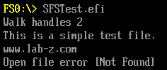
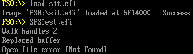
首先,编写测试用的 Application,用 LocateHandleBuffer 枚举出来所有的 Simple File System Protocol,然后在找到的 Handle 上用 OpenVolume 打开 Root Directory。打开之后再用Open 函数打开文件,最后用 Read 来读取文件内容并且显示出来。实验中读取的是一个 44 Bytes 长的 Test.txt 文件。
实验环境是 NT32模拟器,我们只在 fs0: 上放置了 test.txt,因此,能找到2个SimpleFileSystemProtcol,第一个能够读取并且显示内容,第二个会出现Open File error 的错误。
接下来,编写我们的“驱动”,为了简单起见,这里并不是一个正经的驱动。对于我们来说,只是需要程序常驻内存,结束之后不希望被释放掉,否则会出现其他程序调用而无法找到函数的情况。因此,我们在 MdeModulePkg 中写程序,编译之后使用 Load 来加载。代码流程如下:
1. 在入口 MyEntryPoint 中查找一个 SimpleFileSystemProtocol,先保存OpenVolume 的实际入口,再用自己编写的 MySimpleFileSystemOpenVolume替换掉这个入口;
2. Application 在调用 OpenVolume 函数的时候,实际上是会进入MySimpleFileSystemOpenVolume 中。在这个函数中,使用之前保存的实际OpenVolume完成工作,然后将 OpenVolume返回的EFI_FILE_PROTOCOL替换为 MySimpleFileSystemOpen;
3. Application在调用 Open 函数的时候,实际上是会进入MySimpleFileSystemOpen。我们在这里检查参数判断要打开的是否为我们指定的 test.txt 文件,如果是,那么用 MySimpleFileSystemOpen来替换实际的 Open 函数;
4. 这样,当 Application 要Read test.txt 的时候,我们就可以送一个假的值出去。这样就实现了替换的功能。
完整的代码:
用于测试的 Application
#include  <Uefi.h>
#include  <Library/UefiLib.h>
#include  <Library/ShellCEntryLib.h>
#include  <Library/BaseMemoryLib.h>
#include  <Protocol/SimpleFileSystem.h>
#include  <Library/MemoryAllocationLib.h>

extern EFI_RUNTIME_SERVICES      *gRT;
extern EFI_BOOT_SERVICES         *gBS;

int
EFIAPI
main (
  IN int Argc,
  IN CHAR16 **Argv
  )
{

    EFI_STATUS Status;
    EFI_HANDLE  *HandleBuffer = NULL;
    UINTN       NumHandles;
    UINTN       Index;
    EFI_FILE_IO_INTERFACE *ioDevice;
    EFI_FILE_HANDLE handleRoots;
    EFI_FILE_PROTOCOL *TestFile;
    CHAR8      Buffer[4*1024];
    UINTN      BufferSize;

    //Find all Simnple File System Protocol Handle
    Status = gBS->LocateHandleBuffer(
        ByProtocol,
        &gEfiSimpleFileSystemProtocolGuid,
        NULL,
        &NumHandles,
        &HandleBuffer);

    Print(L"Walk handles %ld\n", NumHandles);
    for(Index =0; Index<NumHandles; Index++){
        //Get one Simple File Protocol from a Handle
        Status = gBS->HandleProtocol (
                        HandleBuffer[Index],
                        &gEfiSimpleFileSystemProtocolGuid,
                        (VOID **) &ioDevice
                        );
        //Opens the root directory on the volume
        Status = ioDevice->OpenVolume( ioDevice, &handleRoots );
        if (EFI_ERROR(Status)) {
                Print(L"OpenVolume error \n");
        }
        //Open a file
        Status = handleRoots->Open(handleRoots,&TestFile,L"test.txt",EFI_FILE_MODE_READ, 0);
        if (!EFI_ERROR(Status)) {
                //The size of "Test.txt" is 44bytes, I use hard code here
                BufferSize=44;
                TestFile->Read(TestFile,&BufferSize,&Buffer);
                Print(L"%a",Buffer);
                TestFile->Close(TestFile);
        }
        else
        {
                Print(L"Open file error [%r]\n",Status);
        }
    }

  FreePool (HandleBuffer);

  return EFI_SUCCESS;
}
简单的“驱动” 代码
#include <PiDxe.h>
#include <Library/UefiLib.h>
#include <Library/UefiBootServicesTableLib.h>
#include <Library/DebugLib.h>
#include <Library/UefiDriverEntryPoint.h>
#include <Library/MemoryAllocationLib.h>
#include <Protocol/SimpleFileSystem.h>
#include <Library/MemoryAllocationLib.h>

extern EFI_SYSTEM_TABLE         *gST;

EFI_GUID        gEfiSimpleFileSystemProtocolGuid ={ 0x964E5B22, 0x6459, 0x11D2,
                        { 0x8E, 0x39, 0x00, 0xA0, 0xC9, 0x69, 0x72, 0x3B }};

//Backup of Read function
EFI_FILE_READ OldSimpleFileSystemRead;
//Backup of Open function
EFI_FILE_OPEN OldSimpleFileSystemOpen;
EFI_SIMPLE_FILE_SYSTEM_PROTOCOL_OPEN_VOLUME         OldSimpleFileSystemOpenVolume;

//This one will replace the Read function of Read in Simple File System
EFI_STATUS
EFIAPI
MySimpleFileSystemRead (
  IN     EFI_FILE_PROTOCOL  *This,
  IN OUT UINTN              *BufferSize,
  OUT    VOID               *Buffer
)
{
     CHAR8   TestBuffer[]="Replaced buffer\n\r";
     AsciiStrCpyS(Buffer,AsciiStrnLenS(TestBuffer,255)+1,TestBuffer);
     return EFI_SUCCESS;
}

//This one will replace the Open function of Open in Simple File System
EFI_STATUS
EFIAPI
MySimpleFileSystemOpen (
  IN  EFI_FILE_PROTOCOL  *This,
  OUT EFI_FILE_PROTOCOL  **NewHandle,
  IN  CHAR16             *FileName,
  IN  UINT64             OpenMode,
  IN  UINT64             Attributes
  )
{
        EFI_STATUS Status;

        //Call into Open function in the Simple File system
        Status=(*OldSimpleFileSystemOpen)(This,NewHandle,FileName,OpenMode,Attributes);
        if (!EFI_ERROR(Status)) {
                //Check the filename to make sure it's the one we will replace
                if (StrnCmp(FileName,L"test.txt",StrLen(FileName))==0) {
                        if ((**NewHandle).Read!=MySimpleFileSystemRead) {
                                //Backup the Read Function
                                OldSimpleFileSystemRead=(**NewHandle).Read;
                                //Replace the Read Function
                                (**NewHandle).Read=MySimpleFileSystemRead;
                        }

                }
        }
       return Status;
}


EFI_STATUS
EFIAPI
MySimpleFileSystemOpenVolume (
  IN EFI_SIMPLE_FILE_SYSTEM_PROTOCOL  *This,
  OUT EFI_FILE_PROTOCOL               **Root
  )
{
        EFI_STATUS Status;

        Status=(*OldSimpleFileSystemOpenVolume)(This,Root);

        if (!EFI_ERROR(Status)) {
                if ((**Root).Open!=MySimpleFileSystemOpen) {
                        OldSimpleFileSystemOpen=(**Root).Open;
                        (**Root).Open=MySimpleFileSystemOpen;
                }
        }
       return Status;
}
EFI_STATUS
EFIAPI
MyEntryPoint (
  IN EFI_HANDLE           ImageHandle,
  IN EFI_SYSTEM_TABLE     *SystemTable
  )
{
        EFI_STATUS        Status;
        //EFI_FILE_PROTOCOL *Root;
        EFI_SIMPLE_FILE_SYSTEM_PROTOCOL *SimpleFile;

        //Look for one Simple File System Protocol
        Status = gBS->LocateProtocol (
                        &gEfiSimpleFileSystemProtocolGuid,
                        NULL,
                        &SimpleFile);
        if (EFI_ERROR(Status)) {
           gST->ConOut->OutputString(gST->ConOut,L"Can't find Simple File PROTOCOL\n");
           return Status;
        }
        OldSimpleFileSystemOpenVolume=SimpleFile->OpenVolume;
        SimpleFile->OpenVolume=MySimpleFileSystemOpenVolume;

        return Status;
}
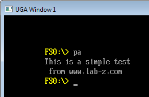
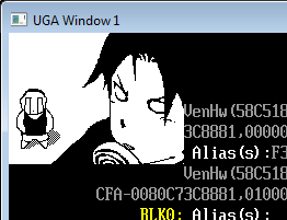
运行结果:
完整的代码下载:
repfun