在进入Windows之后,Runtime Service 和 ACPI Table之类的仍然存在于内存中,但是Windows没有提供标准的方法进行访问。用户能获得的只有经过包装之后 ACPI Table (实际上是来自注册表) ,或者根本就没有提供(比如:Runtime Service Table)。如果想再次获得这样的信息,只能通过扫描系统保留内存来完成。但是 Windows 没有提供类似 E820 的机制告知用户(应该是因为这种信息对于用户来说是根本无需了解的)。经过一段时间的研究,找到了在 Windows下获得系统保留内存的方法:在注册表 HKLM\HARDWARE\RESOURCEMAP\System Resources\Loader Reserved的位置。以我目前使用的笔记本电脑为例,打开这个位置之后可以看到
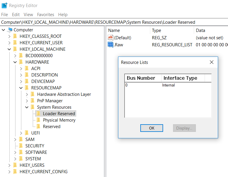
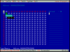
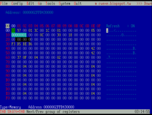
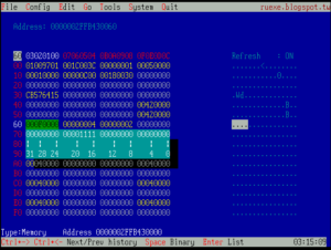
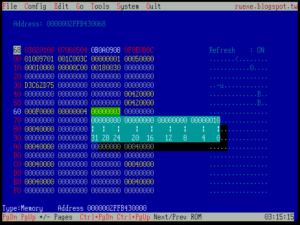
在双击进入即可看到保留内存的信息:
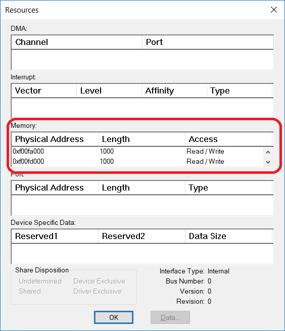
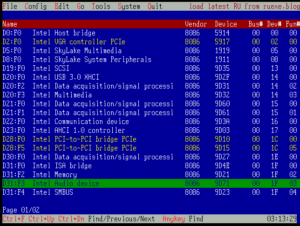
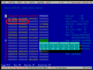
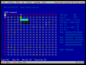
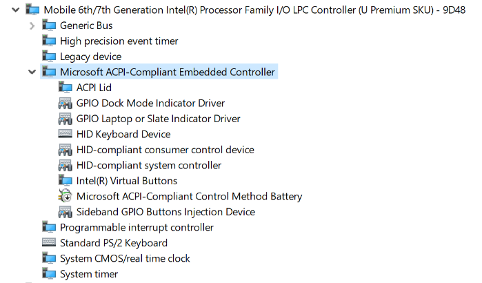
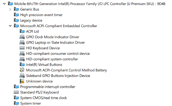
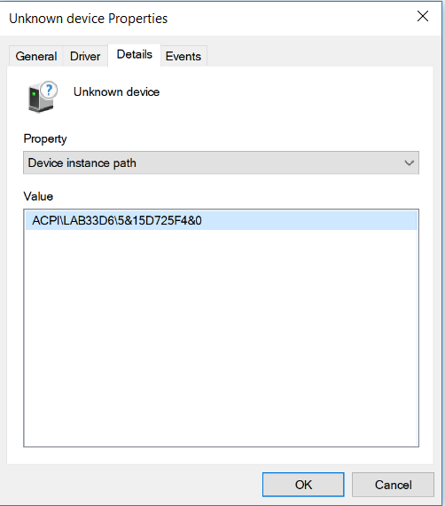
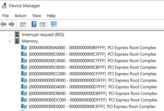
此外,Device Manager中也会给出硬件占用的内存地址,但是这个和系统的保留内存是没有任何关系的。
前面给出了注册表的位置,接下来就是如何解析的问题。
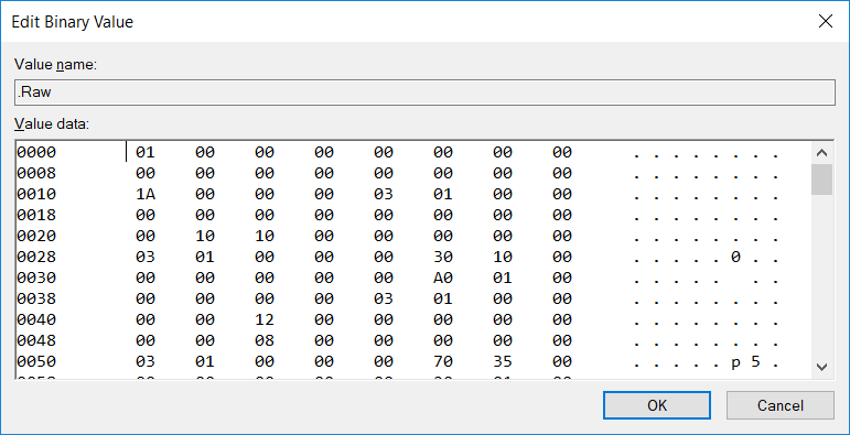
CM_RESOURCE_LIST structure 【参考1】
typedef struct _CM_RESOURCE_LIST {
  ULONG                       Count;
  CM_FULL_RESOURCE_DESCRIPTOR List[1];
} CM_RESOURCE_LIST, *PCM_RESOURCE_LIST;
接下来是下面这个结构体【参考2】
typedef struct _CM_FULL_RESOURCE_DESCRIPTOR {
	INTERFACE_TYPE InterfaceType; // unused for WDM   == 0
	ULONG BusNumber; // unused for WDM
	CM_PARTIAL_RESOURCE_LIST PartialResourceList;
} CM_FULL_RESOURCE_DESCRIPTOR, *PCM_FULL_RESOURCE_DESCRIPTOR;
继续解析【参考3】。其中 ULONG 占用 4BYTES;USHORT占用2BYTES;UCHAR占用1BYTES.
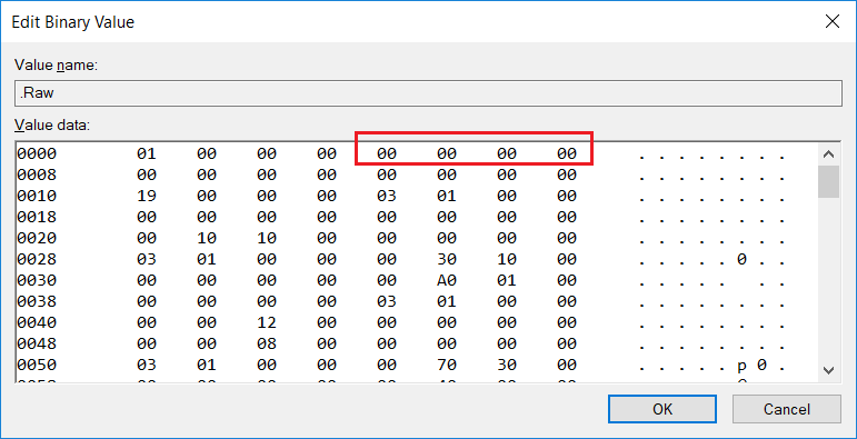
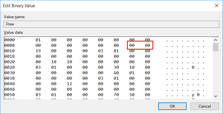
typedef struct _CM_PARTIAL_RESOURCE_LIST {
	USHORT Version;   == 00
	USHORT Revision;
	ULONG Count;
	CM_PARTIAL_RESOURCE_DESCRIPTOR PartialDescriptors[1];
} CM_PARTIAL_RESOURCE_LIST, *PCM_PARTIAL_RESOURCE_LIST;
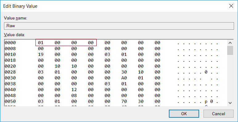
USHORT Version ==00

USHORT Revision ==00
Count=0x19
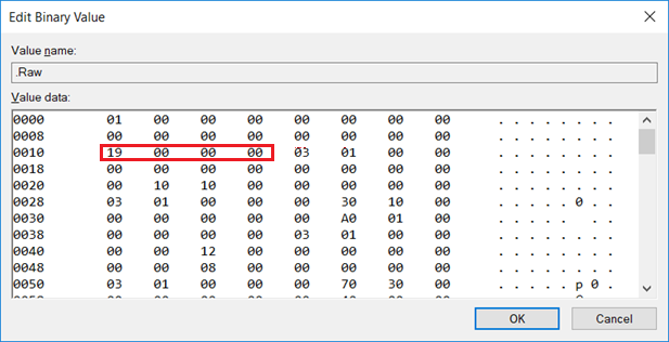
接下来就是每一个保留的内存情况
CM_PARTIAL_RESOURCE_DESCRIPTOR structure【参考4】
typedef struct _CM_PARTIAL_RESOURCE_DESCRIPTOR {
  UCHAR  Type;
  UCHAR  ShareDisposition;
  USHORT Flags;
  union {
………………
………………
………………
}
根据上面的方法即可获得当前系统中 Loader 通知系统的 Reserved Memory
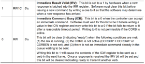
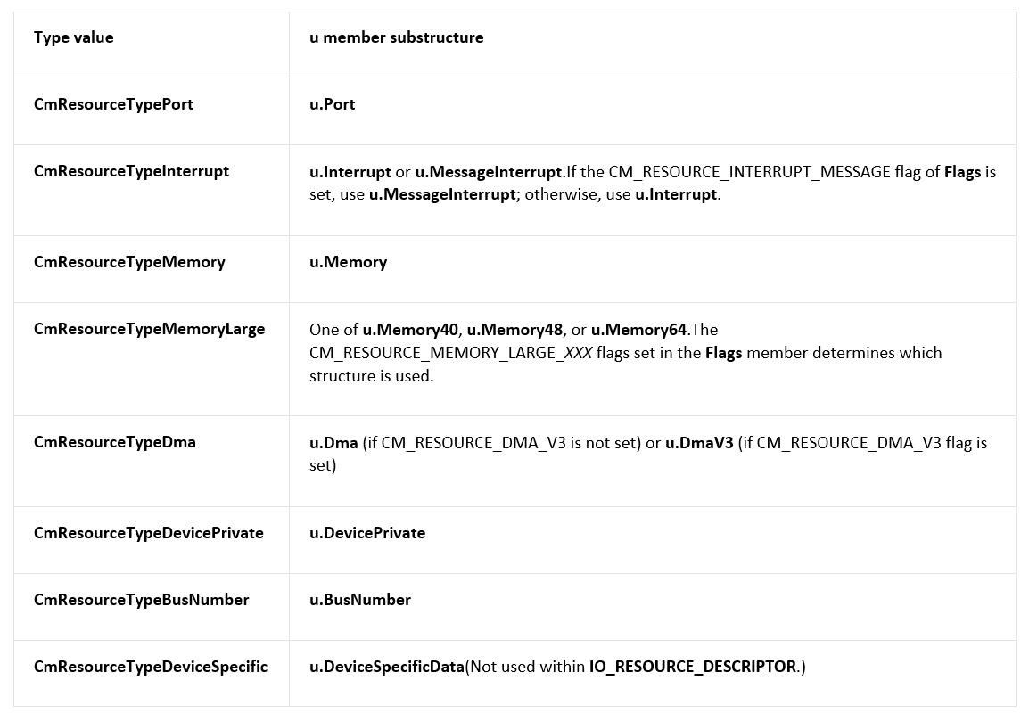
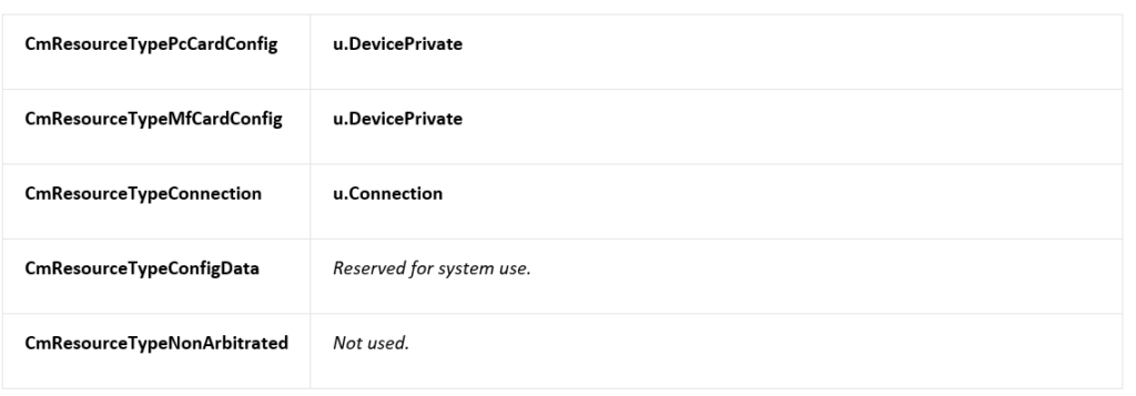
对于 type的定义在【参考5】
Identifies the resource type. The constant value specified for Type indicates which structure within the u union is valid, as indicated in the following table. (These flags are used within both CM_PARTIAL_RESOURCE_DESCRIPTORand IO_RESOURCE_DESCRIPTOR structures, except where noted.)

有了上面的基础就可以编写代码:
// ConsoleApplication3.cpp : Defines the entry point for the console application.
//

#include "stdafx.h"
#include <Windows.h>
#include <strsafe.h>
#include <tchar.h>

HKEY m_hKey;

#define OffSet(type, field) ((size_t)&(((type*)0)->field))

#pragma pack(1)
//
// Physical address.
//

typedef LARGE_INTEGER PHYSICAL_ADDRESS, *PPHYSICAL_ADDRESS;

typedef struct _CM_PARTIAL_RESOURCE_DESCRIPTOR {
	UCHAR Type;
	UCHAR ShareDisposition;
	USHORT Flags;
	union {

		//
		// Range of resources, inclusive.  These are physical, bus relative.
		// It is known that Port and Memory below have the exact same layout
		// as Generic.
		//

		struct {
			PHYSICAL_ADDRESS Start;
			ULONG Length;
		} Generic;

		//
		//

		struct {
			PHYSICAL_ADDRESS Start;
			ULONG Length;
		} Port;

		//
		//

		struct {
#if defined(NT_PROCESSOR_GROUPS)
			USHORT Level;
			USHORT Group;
#else
			ULONG Level;
#endif
			ULONG Vector;
			KAFFINITY Affinity;
		} Interrupt;

		//
		// Values for message signaled interrupts are distinct in the
		// raw and translated cases.
		//

		struct {
			union {
				struct {
#if defined(NT_PROCESSOR_GROUPS)
					USHORT Group;
#else
					USHORT Reserved;
#endif
					USHORT MessageCount;
					ULONG Vector;
					KAFFINITY Affinity;
				} Raw;

				struct {
#if defined(NT_PROCESSOR_GROUPS)
					USHORT Level;
					USHORT Group;
#else
					ULONG Level;
#endif
					ULONG Vector;
					KAFFINITY Affinity;
				} Translated;
			} DUMMYUNIONNAME;
		} MessageInterrupt;

		//
		// Range of memory addresses, inclusive. These are physical, bus
		// relative. The value should be the same as the one passed to
		// HalTranslateBusAddress().
		//

		struct {
			PHYSICAL_ADDRESS Start;    // 64 bit physical addresses.
			ULONG Length;
		} Memory;

		//
		// Physical DMA channel.
		//

		struct {
			ULONG Channel;
			ULONG Port;
			ULONG Reserved1;
		} Dma;

		struct {
			ULONG Channel;
			ULONG RequestLine;
			UCHAR TransferWidth;
			UCHAR Reserved1;
			UCHAR Reserved2;
			UCHAR Reserved3;
		} DmaV3;

		//
		// Device driver private data, usually used to help it figure
		// what the resource assignments decisions that were made.
		//

		struct {
			ULONG Data[3];
		} DevicePrivate;

		//
		// Bus Number information.
		//

		struct {
			ULONG Start;
			ULONG Length;
			ULONG Reserved;
		} BusNumber;

		//
		// Device Specific information defined by the driver.
		// The DataSize field indicates the size of the data in bytes. The
		// data is located immediately after the DeviceSpecificData field in
		// the structure.
		//

		struct {
			ULONG DataSize;
			ULONG Reserved1;
			ULONG Reserved2;
		} DeviceSpecificData;

		// The following structures provide support for memory-mapped
		// IO resources greater than MAXULONG
		struct {
			PHYSICAL_ADDRESS Start;
			ULONG Length40;
		} Memory40;

		struct {
			PHYSICAL_ADDRESS Start;
			ULONG Length48;
		} Memory48;

		struct {
			PHYSICAL_ADDRESS Start;
			ULONG Length64;
		} Memory64;

		struct {
			UCHAR Class;
			UCHAR Type;
			UCHAR Reserved1;
			UCHAR Reserved2;
			ULONG IdLowPart;
			ULONG IdHighPart;
		} Connection;

	} u;
} CM_PARTIAL_RESOURCE_DESCRIPTOR, *PCM_PARTIAL_RESOURCE_DESCRIPTOR;

//
// A Partial Resource List is what can be found in the ARC firmware
// or will be generated by ntdetect.com.
// The configuration manager will transform this structure into a Full
// resource descriptor when it is about to store it in the regsitry.
//
// Note: There must a be a convention to the order of fields of same type,
// (defined on a device by device basis) so that the fields can make sense
// to a driver (i.e. when multiple memory ranges are necessary).
//

typedef struct _CM_PARTIAL_RESOURCE_LIST {
	USHORT Version;
	USHORT Revision;
	ULONG Count;
	CM_PARTIAL_RESOURCE_DESCRIPTOR PartialDescriptors[1];
} CM_PARTIAL_RESOURCE_LIST, *PCM_PARTIAL_RESOURCE_LIST;

//
// Define the I/O bus interface types.
//

typedef enum _INTERFACE_TYPE {
	InterfaceTypeUndefined = -1,
	Internal,
	Isa,
	Eisa,
	MicroChannel,
	TurboChannel,
	PCIBus,
	VMEBus,
	NuBus,
	PCMCIABus,
	CBus,
	MPIBus,
	MPSABus,
	ProcessorInternal,
	InternalPowerBus,
	PNPISABus,
	PNPBus,
	Vmcs,
	ACPIBus,
	MaximumInterfaceType
}INTERFACE_TYPE, *PINTERFACE_TYPE;

//
// A Full Resource Descriptor is what can be found in the registry.
// This is what will be returned to a driver when it queries the registry
// to get device information; it will be stored under a key in the hardware
// description tree.
//
// Note: There must a be a convention to the order of fields of same type,
// (defined on a device by device basis) so that the fields can make sense
// to a driver (i.e. when multiple memory ranges are necessary).
//

typedef struct _CM_FULL_RESOURCE_DESCRIPTOR {
	INTERFACE_TYPE InterfaceType; // unused for WDM
	ULONG BusNumber; // unused for WDM
	CM_PARTIAL_RESOURCE_LIST PartialResourceList;
} CM_FULL_RESOURCE_DESCRIPTOR, *PCM_FULL_RESOURCE_DESCRIPTOR;


//
// The Resource list is what will be stored by the drivers into the
// resource map via the IO API.
//

typedef struct _CM_RESOURCE_LIST {
	ULONG Count;
	CM_FULL_RESOURCE_DESCRIPTOR List[1];
} CM_RESOURCE_LIST, *PCM_RESOURCE_LIST;

int main()
{
	DWORD Index;
	BYTE  *v;

	if (RegOpenKeyEx(
			HKEY_LOCAL_MACHINE,
			TEXT("HARDWARE\\RESOURCEMAP\\System Resources\\Loader Reserved"),
			0,
			KEY_READ,
			&m_hKey) != ERROR_SUCCESS)
	{
		printf("RegOpenKeyEx fail \n");
		getchar();
		exit(0);
	}

	BOOL bRet = FALSE;
	LPSTR lpstrValue;
	DWORD dwType = REG_SZ;
	DWORD lpcbData;
	DWORD r;

	r = RegQueryValueEx(m_hKey,
		TEXT(".Raw"),
		NULL,
		&dwType,
		NULL,
		&lpcbData);
	if (r != ERROR_SUCCESS)
	{
		printf("Can't get data from registry\n");
		getchar();
		exit(0);
	}
	bRet = FALSE;
	lpstrValue = (LPSTR)malloc(lpcbData);

	r = RegQueryValueEx(m_hKey,
		TEXT(".Raw"),
		NULL,
		&dwType,
		(BYTE*)(LPCTSTR)lpstrValue,
		&lpcbData);
	if (r != ERROR_SUCCESS)
	{
		printf("fail\n");
		getchar();
		exit(0);
	}

	for (Index = 0; Index < lpcbData; Index++) {
		if (Index % 16 == 0) { printf("\n"); }
		v = (BYTE*)lpstrValue;
		printf("%02X ", *(v + Index));

	}

	PCM_RESOURCE_LIST res= (PCM_RESOURCE_LIST)lpstrValue;
	PCM_PARTIAL_RESOURCE_LIST Partial;
	DWORD  Index1;

	for (Index = 0; Index < res->Count; Index++)
	{
		printf("\nInteface type: %d\n Bus Number: %d\n",
				res->List[Index].InterfaceType,
			    res->List[Index].BusNumber);
		Partial = (PCM_PARTIAL_RESOURCE_LIST) &res->List[Index].PartialResourceList;
		printf(" Version: %d\n Revision: %d\n Counter: %x\n",
			Partial->Version,
			Partial->Revision,
			Partial->Count);
		for (Index1 = 0; Index1 < Partial->Count; Index1++) {
			//printf("%d\n", Partial->PartialDescriptors[Index1].Type);
			if (Partial->PartialDescriptors[Index1].Type == 3) {
				printf("Start:%016I64x Length:%x \n",
						Partial->PartialDescriptors[Index1].u.Memory.Start,
						Partial->PartialDescriptors[Index1].u.Memory.Length
					);
			}
		}
	}
	free(lpstrValue);
	getchar();
    return 0;
}
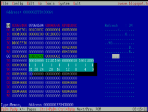
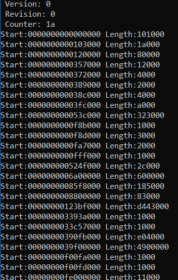
运行结果如下(运行的机器和之前做分析的不同,所以 Counter数量不同)
参考:
1. https://msdn.microsoft.com/en-us/library/windows/hardware/ff541994(v=vs.85).aspx
2. https://msdn.microsoft.com/en-us/library/windows/hardware/ff541954(v=vs.85).aspx
3. https://msdn.microsoft.com/en-us/library/windows/hardware/ff541981(v=vs.85).aspx
4. https://msdn.microsoft.com/en-us/library/windows/hardware/ff541977(v=vs.85).aspx
5. https://docs.microsoft.com/en-us/windows-hardware/drivers/ddi/content/wdm/ns-wdm-_cm_partial_resource_descriptor