一些情况下,我们需要得知操作消耗的时间,比如:通过硬盘读写操作耗费的时间能够计算出硬盘的速度。针对这个问题,之前有过研究,例如:GetTime 研究【参考1】、EADK clock()【参考2】。这里再次进行研究。
首先,在MdePkg\Include\Library\TimerLib.h给出了下面两个函数:
/**
  Retrieves the current value of a 64-bit free running performance counter.
  The counter can either count up by 1 or count down by 1. If the physical
  performance counter counts by a larger increment, then the counter values
  must be translated. The properties of the counter can be retrieved from
  GetPerformanceCounterProperties().
  @return The current value of the free running performance counter.
**/
UINT64
EFIAPI
GetPerformanceCounter (
  VOID
  );
/**
  Converts elapsed ticks of performance counter to time in nanoseconds.
  This function converts the elapsed ticks of running performance counter to
  time value in unit of nanoseconds.
  @param  Ticks     The number of elapsed ticks of running performance counter.
  @return The elapsed time in nanoseconds.
**/
UINT64
EFIAPI
GetTimeInNanoSecond (
  IN      UINT64  Ticks
  );
/**
  Retrieves the current value of a 64-bit free running performance counter.
  The counter can either count up by 1 or count down by 1. If the physical
  performance counter counts by a larger increment, then the counter values
  must be translated. The properties of the counter can be retrieved from
  GetPerformanceCounterProperties().
  @return The current value of the free running performance counter.
**/
UINT64
EFIAPI
GetPerformanceCounter (
  VOID
  );
/**
  Converts elapsed ticks of performance counter to time in nanoseconds.
  This function converts the elapsed ticks of running performance counter to
  time value in unit of nanoseconds.
  @param  Ticks     The number of elapsed ticks of running performance counter.
  @return The elapsed time in nanoseconds.
**/
UINT64
EFIAPI
GetTimeInNanoSecond (
  IN      UINT64  Ticks
  );
其中的GetPerformanceCounter() 返回CPU 当前经过的计数值或者说多少个 Ticks,GetTimeInNanoSecond() 函数能将经过的计数值转化为纳秒为单位的时间。
编写一个 UEFI Shell代码进行测试:
1. 在AppPkg.dsc 中加入 TimerLib
CacheMaintenanceLib|MdePkg/Library/BaseCacheMaintenanceLib/BaseCacheMaintenanceLib.inf
  TimerLib|UefiCpuPkg/Library/CpuTimerLib/BaseCpuTimerLib.inf
###################################################################################################
#
# Components Section - list of the modules and components that will be processed by compilation
#
2.编写代码如下:
#include  <Uefi.h>
#include  <Library/UefiLib.h>
#include  <Library/ShellCEntryLib.h>
#include  <Library/TimerLib.h>
#include  <Library/UefiBootServicesTableLib.h>
INTN
EFIAPI
ShellAppMain (
  IN UINTN Argc,
  IN CHAR16 **Argv
  )
{
	UINT64	Start=GetPerformanceCounter();
	gBS->Stall(1000000UL);
	Print(L"You have dealyed [%llu]ns\n",
			GetTimeInNanoSecond(GetPerformanceCounter()-Start));
  return(0);
}
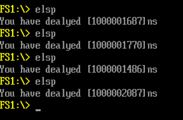
具体动作就是首先保存当前的 CPU 计数值,然后延时 1s, 最后输出以纳秒为单位的经过时间。可以看到每次运行耗时会有一点波动。
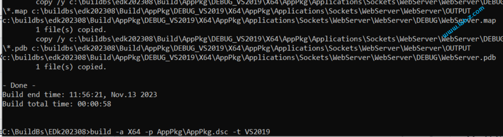
因为没有使用 CLIB , 所以 Build出来代码体积也比较小,只有9KB.
参考: