来自 https://msdn.microsoft.com/en-us/library/aa390423(v=vs.85).aspx
特别注意取得的 WMI 的 String 是 Unicode 的,输出时需要使用 %ls
#include “stdafx.h”
#define _WIN32_DCOM
#include
#include
#pragma comment(lib, “wbemuuid.lib”)
int main(int argc, char **argv)
{
HRESULT hres;
// Step 1: ————————————————–
// Initialize COM. ——————————————
hres = CoInitializeEx(0, COINIT_MULTITHREADED);
if (FAILED(hres))
{
printf(“Failed to initialize COM library. Error code”);
return 1; // Program has failed.
}
// Step 2: ————————————————–
// Set general COM security levels ————————–
hres = CoInitializeSecurity(
NULL,
-1, // COM authentication
NULL, // Authentication services
NULL, // Reserved
RPC_C_AUTHN_LEVEL_DEFAULT, // Default authentication
RPC_C_IMP_LEVEL_IMPERSONATE, // Default Impersonation
NULL, // Authentication info
EOAC_NONE, // Additional capabilities
NULL // Reserved
);
if (FAILED(hres))
{
printf(“Failed to initialize security. Error code = 0x”);
CoUninitialize();
return 1; // Program has failed.
}
// Step 3: —————————————————
// Obtain the initial locator to WMI ————————-
IWbemLocator *pLoc = NULL;
hres = CoCreateInstance(
CLSID_WbemLocator,
0,
CLSCTX_INPROC_SERVER,
IID_IWbemLocator, (LPVOID *)&pLoc);
if (FAILED(hres))
{
printf(“Failed to create IWbemLocator object.”);
CoUninitialize();
return 1; // Program has failed.
}
// Step 4: —————————————————–
// Connect to WMI through the IWbemLocator::ConnectServer method
IWbemServices *pSvc = NULL;
// Connect to the root\cimv2 namespace with
// the current user and obtain pointer pSvc
// to make IWbemServices calls.
hres = pLoc->ConnectServer(
_bstr_t(L”ROOT\\CIMV2″), // Object path of WMI namespace
NULL, // User name. NULL = current user
NULL, // User password. NULL = current
0, // Locale. NULL indicates current
NULL, // Security flags.
0, // Authority (for example, Kerberos)
0, // Context object
&pSvc // pointer to IWbemServices proxy
);
if (FAILED(hres))
{
printf(“Could not connect. Error code = 0x”);
pLoc->Release();
CoUninitialize();
return 1; // Program has failed.
}
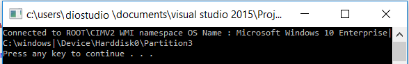
printf(“Connected to ROOT\\CIMV2 WMI namespace”);
// Step 5: ————————————————–
// Set security levels on the proxy ————————-
hres = CoSetProxyBlanket(
pSvc, // Indicates the proxy to set
RPC_C_AUTHN_WINNT, // RPC_C_AUTHN_xxx
RPC_C_AUTHZ_NONE, // RPC_C_AUTHZ_xxx
NULL, // Server principal name
RPC_C_AUTHN_LEVEL_CALL, // RPC_C_AUTHN_LEVEL_xxx
RPC_C_IMP_LEVEL_IMPERSONATE, // RPC_C_IMP_LEVEL_xxx
NULL, // client identity
EOAC_NONE // proxy capabilities
);
if (FAILED(hres))
{
printf(“Could not set proxy blanket. Error code = 0x”);
pSvc->Release();
pLoc->Release();
CoUninitialize();
return 1; // Program has failed.
}
// Step 6: ————————————————–
// Use the IWbemServices pointer to make requests of WMI —-
// For example, get the name of the operating system
IEnumWbemClassObject* pEnumerator = NULL;
hres = pSvc->ExecQuery(
bstr_t(“WQL”),
bstr_t(“SELECT * FROM Win32_OperatingSystem”),
WBEM_FLAG_FORWARD_ONLY | WBEM_FLAG_RETURN_IMMEDIATELY,
NULL,
&pEnumerator);
if (FAILED(hres))
{
printf(“Query for operating system name failed.”);
pSvc->Release();
pLoc->Release();
CoUninitialize();
return 1; // Program has failed.
}
// Step 7: ————————————————-
// Get the data from the query in step 6 ——————-
IWbemClassObject *pclsObj = NULL;
ULONG uReturn = 0;
while (pEnumerator)
{
HRESULT hr = pEnumerator->Next(WBEM_INFINITE, 1,
&pclsObj, &uReturn);
if (0 == uReturn)
{
break;
}
VARIANT vtProp;
// Get the value of the Name property
hr = pclsObj->Get(L”Name”, 0, &vtProp, 0, 0);
//wcout << " OS Name : " << vtProp.bstrVal << endl;
printf(" OS Name : %ls\n", vtProp.bstrVal);
VariantClear(&vtProp);
pclsObj->Release();
}
// Cleanup
// ========
pSvc->Release();
pLoc->Release();
pEnumerator->Release();
CoUninitialize();
system(“PAUSE”);
return 0; // Program successfully completed.
}
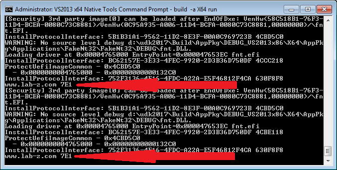
运行结果 (VS2015 Windows 10 RS1)