有些情况下,我们需要在命令行下刷写 Leonardo 的 Firmware,一般的方法会遇到问题,原因是 Leonardo 进入 Bootloader 的方式比较特别:使用 1200波特率打开串口,Leonardo立即开始重启,重启之后运行的Booloader会让串口变化成为另外的编号,在这个过程中如果有握手,那么就开始 Firmware 的更新。因为中间串口会发生变化,因此一般的刷新方法都会都会碰到问题。
最近,我在网上网上看到了一个高手编写的代码,能够在 Windows下实现全自动的命令行刷写https://github.com/p1ne/arduino-leonardo-uploader/tree/master/windows
核心是一个 BAT 批处理文件,首先用 WMI 在系统中查找包含 Leonardo 字样的串口,然后用 mode 来设置这个串口,这样 Leonardo 就会去Reset。接下来再使用 WMI 在系统中查找Leonardo Bootloader 的字样确定新出现的串口号。然后就用 avrdude 来进行正常刷写了。
具体代码如下,相信看懂并不困难:
rem @echo off
setlocal

for /f "tokens=1* delims==" %%I in ('wmic path win32_pnpentity get caption  /format:list ^| find "Arduino"') do (
    call :resetCOM "%%~J"
)

:continue

:: wmic /format:list strips trailing spaces (at least for path win32_pnpentity)
for /f "tokens=1* delims==" %%I in ('wmic path win32_pnpentity get caption  /format:list ^| find "Arduino Leonardo bootloader"') do (
    call :setCOM "%%~J"
)

:: end main batch
goto :EOF

:resetCOM <WMIC_output_line>
:: sets _COM#=line
setlocal
set "str=%~1"
set "num=%str:*(COM=%"
set "num=%num:)=%"
set port=COM%num%
echo %port%
mode %port%: BAUD=1200 parity=N data=8 stop=1
timeout /t 1
goto :continue

:setCOM <WMIC_output_line>
:: sets _COM#=line
setlocal
set "str=%~1"
set "num=%str:*(COM=%"
set "num=%num:)=%"
set port=COM%num%
echo %port%
goto :flash

:flash
avrdude -v -CD:\arduino-1.8.4\hardware\tools\avr\etc\avrdude.conf -patmega32u4 -cavr109 -P%port% -b57600 -D -V -Uflash:w:./blink.ino.hex:i
特别注意的是:
1. 如果你在 Win10 上使用并且没有安装 Leonardo 驱动的话,设备名称不会出来 Arduino 字样,安装2个驱动(一个是 Bootloader的,一个是 Arduino 本身的)之后即可正常工作;
2. 注意最后 avrdude.conf 的路径不要搞错了
3. 要刷写的文件也是在最后一条命令上,我这里使用的是blink.ino.hex:i
我这边实验的结果如下:
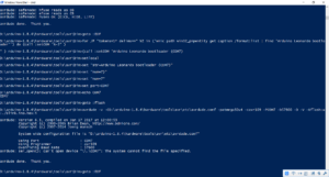
完整的log 如下:
D:\arduino-1.8.4\hardware\tools\avr\bin>f
D:\arduino-1.8.4\hardware\tools\avr\bin>rem @echo off
D:\arduino-1.8.4\hardware\tools\avr\bin>setlocal
D:\arduino-1.8.4\hardware\tools\avr\bin>for /F “tokens=1* delims==” %I in (‘wmic path win32_pnpentity get caption /format:list | find “Arduino”‘) do (call :resetCOM “%~J” )
” ) rduino-1.8.4\hardware\tools\avr\bin>(call :resetCOM “Arduino Leonardo (COM9)
D:\arduino-1.8.4\hardware\tools\avr\bin>setlocal
D:\arduino-1.8.4\hardware\tools\avr\bin>set “str=Arduino Leonardo (COM9)”
D:\arduino-1.8.4\hardware\tools\avr\bin>set “num=9)”
D:\arduino-1.8.4\hardware\tools\avr\bin>set “num=9”
D:\arduino-1.8.4\hardware\tools\avr\bin>set port=COM9
D:\arduino-1.8.4\hardware\tools\avr\bin>echo COM9
COM9
D:\arduino-1.8.4\hardware\tools\avr\bin>mode COM9: BAUD=1200 parity=N data=8 stop=1
Status for device COM9:
———————–
Baud: 1200
Parity: None
Data Bits: 8
Stop Bits: 1
Timeout: OFF
XON/XOFF: OFF
CTS handshaking: OFF
DSR handshaking: OFF
DSR sensitivity: OFF
DTR circuit: OFF
RTS circuit: ON
D:\arduino-1.8.4\hardware\tools\avr\bin>timeout /t 1
Waiting for 0 seconds, press a key to continue …
D:\arduino-1.8.4\hardware\tools\avr\bin>goto :continue
D:\arduino-1.8.4\hardware\tools\avr\bin>for /F “tokens=1* delims==” %I in (‘wmic path win32_pnpentity get caption /format:list | find “Arduino Leonardo bootloader”‘) do (call :setCOM “%~J” )
” ) rduino-1.8.4\hardware\tools\avr\bin>(call :setCOM “Arduino Leonardo bootloader (COM7)
D:\arduino-1.8.4\hardware\tools\avr\bin>setlocal
D:\arduino-1.8.4\hardware\tools\avr\bin>set “str=Arduino Leonardo bootloader (COM7)”
D:\arduino-1.8.4\hardware\tools\avr\bin>set “num=7)”
D:\arduino-1.8.4\hardware\tools\avr\bin>set “num=7”
D:\arduino-1.8.4\hardware\tools\avr\bin>set port=COM7
D:\arduino-1.8.4\hardware\tools\avr\bin>echo COM7
COM7
D:\arduino-1.8.4\hardware\tools\avr\bin>goto :flash
D:\arduino-1.8.4\hardware\tools\avr\bin>avrdude -v -CD:\arduino-1.8.4\hardware\tools\avr\etc\avrdude.conf -patmega32u4 -cavr109 -PCOM7 -b57600 -D -V -Uflash:w:./blink.ino.hex:i
avrdude: Version 6.3, compiled on Jan 17 2017 at 12:00:53
Copyright (c) 2000-2005 Brian Dean, http://www.bdmicro.com/
Copyright (c) 2007-2014 Joerg Wunsch
System wide configuration file is “D:\arduino-1.8.4\hardware\tools\avr\etc\avrdude.conf”
Using Port : COM7
Using Programmer : avr109
Overriding Baud Rate : 57600
AVR Part : ATmega32U4
Chip Erase delay : 9000 us
PAGEL : PD7
BS2 : PA0
RESET disposition : dedicated
RETRY pulse : SCK
serial program mode : yes
parallel program mode : yes
Timeout : 200
StabDelay : 100
CmdexeDelay : 25
SyncLoops : 32
ByteDelay : 0
PollIndex : 3
PollValue : 0x53
Memory Detail :
Block Poll Page Polled
Memory Type Mode Delay Size Indx Paged Size Size #Pages MinW MaxW ReadBack
———– —- —– —– —- —— —— —- —— —– —– ———
eeprom 65 20 4 0 no 1024 4 0 9000 9000 0x00 0x00
flash 65 6 128 0 yes 32768 128 256 4500 4500 0x00 0x00
lfuse 0 0 0 0 no 1 0 0 9000 9000 0x00 0x00
hfuse 0 0 0 0 no 1 0 0 9000 9000 0x00 0x00
efuse 0 0 0 0 no 1 0 0 9000 9000 0x00 0x00
lock 0 0 0 0 no 1 0 0 9000 9000 0x00 0x00
calibration 0 0 0 0 no 1 0 0 0 0 0x00 0x00
signature 0 0 0 0 no 3 0 0 0 0 0x00 0x00
Programmer Type : butterfly
Description : Atmel AppNote AVR109 Boot Loader
Connecting to programmer: .
Found programmer: Id = “CATERIN”; type = S
Software Version = 1.0; No Hardware Version given.
Programmer supports auto addr increment.
Programmer supports buffered memory access with buffersize=128 bytes.
Programmer supports the following devices:
Device code: 0x44
avrdude: devcode selected: 0x44
avrdude: AVR device initialized and ready to accept instructions
Reading | ################################################## | 100% 0.01s
avrdude: Device signature = 0x1e9587 (probably m32u4)
avrdude: safemode: hfuse reads as D8
avrdude: safemode: efuse reads as CB
avrdude: reading input file “./blink.ino.hex”
avrdude: writing flash (4142 bytes):
Writing | ################################################## | 100% 0.68s
avrdude: 4142 bytes of flash written
avrdude: safemode: hfuse reads as D8
avrdude: safemode: efuse reads as CB
avrdude: safemode: Fuses OK (E:CB, H:D8, L:FF)
avrdude done. Thank you.
D:\arduino-1.8.4\hardware\tools\avr\bin>goto :EOF
D:\arduino-1.8.4\hardware\tools\avr\bin>for /F “tokens=1* delims==” %I in (‘wmic path win32_pnpentity get caption /format:list | find “Arduino Leonardo bootloader”‘) do (call :setCOM “%~J” )
” ) rduino-1.8.4\hardware\tools\avr\bin>(call :setCOM “Arduino Leonardo bootloader (COM7)
D:\arduino-1.8.4\hardware\tools\avr\bin>setlocal
D:\arduino-1.8.4\hardware\tools\avr\bin>set “str=Arduino Leonardo bootloader (COM7)”
D:\arduino-1.8.4\hardware\tools\avr\bin>set “num=7)”
D:\arduino-1.8.4\hardware\tools\avr\bin>set “num=7”
D:\arduino-1.8.4\hardware\tools\avr\bin>set port=COM7
D:\arduino-1.8.4\hardware\tools\avr\bin>echo COM7
COM7
D:\arduino-1.8.4\hardware\tools\avr\bin>goto :flash
D:\arduino-1.8.4\hardware\tools\avr\bin>avrdude -v -CD:\arduino-1.8.4\hardware\tools\avr\etc\avrdude.conf -patmega32u4 -cavr109 -PCOM7 -b57600 -D -V -Uflash:w:./blink.ino.hex:i
avrdude: Version 6.3, compiled on Jan 17 2017 at 12:00:53
Copyright (c) 2000-2005 Brian Dean, http://www.bdmicro.com/
Copyright (c) 2007-2014 Joerg Wunsch
System wide configuration file is “D:\arduino-1.8.4\hardware\tools\avr\etc\avrdude.conf”
Using Port : COM7
Using Programmer : avr109
Overriding Baud Rate : 57600
avrdude: ser_open(): can’t open device “\\.\COM7”: The system cannot find the file specified.
avrdude done. Thank you.
D:\arduino-1.8.4\hardware\tools\avr\bin>goto :EOF