/**
  Entry point of Status Code PEIM.

  This function is the entry point of this Status Code Router PEIM.
  It produces Report Stataus Code Handler PPI and Status Code PPI.

  @param  FileHandle  Handle of the file being invoked.
  @param  PeiServices Describes the list of possible PEI Services.

  @retval EFI_SUCESS  The entry point of DXE IPL PEIM executes successfully.

**/
EFI_STATUS
EFIAPI
GenericStatusCodePeiEntry (
  IN       EFI_PEI_FILE_HANDLE  FileHandle,
  IN CONST EFI_PEI_SERVICES     **PeiServices
  )
/**
  Entry point of Status Code PEIM.

  This function is the entry point of this Status Code PEIM.
  It initializes supported status code devices according to PCD settings,
  and installs Status Code PPI.

  @param  FileHandle  Handle of the file being invoked.
  @param  PeiServices Describes the list of possible PEI Services.

  @retval EFI_SUCESS  The entry point of DXE IPL PEIM executes successfully.

**/
EFI_STATUS
EFIAPI
StatusCodeHandlerPeiEntry (
  IN       EFI_PEI_FILE_HANDLE  FileHandle,
  IN CONST EFI_PEI_SERVICES     **PeiServices
  )
{
  EFI_STATUS                  Status;
  EFI_PEI_RSC_HANDLER_PPI     *RscHandlerPpi;

  Status = PeiServicesLocatePpi (
             &gEfiPeiRscHandlerPpiGuid,
             0,
             NULL,
             (VOID **) &RscHandlerPpi
             );
  ASSERT_EFI_ERROR (Status);

  //
  // Dispatch initialization request to sub-statuscode-devices.
  // If enable UseSerial, then initialize serial port.
  // if enable UseMemory, then initialize memory status code worker.
  //
  if (PcdGetBool (PcdStatusCodeUseSerial)) {
    Status = SerialPortInitialize();
    ASSERT_EFI_ERROR (Status);
    Status = RscHandlerPpi->Register (SerialStatusCodeReportWorker);
    ASSERT_EFI_ERROR (Status);
  }
  if (PcdGetBool (PcdStatusCodeUseMemory)) {
    Status = MemoryStatusCodeInitializeWorker ();
    ASSERT_EFI_ERROR (Status);
    Status = RscHandlerPpi->Register (MemoryStatusCodeReportWorker);
    ASSERT_EFI_ERROR (Status);
  }

  return EFI_SUCCESS;
}
/**
  Initialize the security services.

  @param PeiServices     An indirect pointer to the EFI_PEI_SERVICES table published by the PEI Foundation.
  @param OldCoreData     Pointer to the old core data.
                         NULL if being run in non-permanent memory mode.

**/
VOID
InitializeSecurityServices (
  IN EFI_PEI_SERVICES  **PeiServices,
  IN PEI_CORE_INSTANCE *OldCoreData
  )
{
  if (OldCoreData == NULL) {
    PeiServicesNotifyPpi (&mNotifyList);
  }
  return;
}
其中 mNotifyList 注册了一个 Ppi Notify 的 Callback 函数:SecurityPpiNotifyCallback()
/**
  This service enables PEIMs to register a given service to be invoked when another service is
  installed or reinstalled.

  @param  NotifyList            A pointer to the list of notification interfaces
                                that the caller shall install.

  @retval EFI_SUCCESS           The interface was successfully installed.
  @retval EFI_INVALID_PARAMETER The NotifyList pointer is NULL.
  @retval EFI_INVALID_PARAMETER Any of the PEI notify descriptors in the list do
                                 not have the EFI_PEI_PPI_DESCRIPTOR_NOTIFY_TYPES
                                 bit set in the Flags field.
  @retval EFI_OUT_OF_RESOURCES  There is no additional space in the PPI database.

**/
EFI_STATUS
EFIAPI
PeiServicesNotifyPpi (
  IN CONST EFI_PEI_NOTIFY_DESCRIPTOR  *NotifyList
  )
这个函数的功能是:注册一个 Callback函数,当给定的 Service 安装(install)或者重安装(re-install)时触发这个 callback函数。
/**
  Main entry for PCD PEIM driver.

  This routine initialize the PCD database for PEI phase and install PCD_PPI/EFI_PEI_PCD_PPI.

  @param  FileHandle  Handle of the file being invoked.
  @param  PeiServices Describes the list of possible PEI Services.

  @return Status of install PCD_PPI

**/
EFI_STATUS
EFIAPI
PcdPeimInit (
  IN       EFI_PEI_FILE_HANDLE  FileHandle,
  IN CONST EFI_PEI_SERVICES     **PeiServices
  )
从代码上看,QEMU 模拟了 SPI ROM,使可以看到,这个 PEI Module 主要作用是注册了多个和PCD 相关的 Ppi Service 以便后续使用。
MdeModulePkg\Core\Pei\Dispatcher\Dispatcher.c
/**
  Conduct PEIM dispatch.

  @param SecCoreData     Points to a data structure containing information about the PEI core's operating
                         environment, such as the size and location of temporary RAM, the stack location and
                         the BFV location.
  @param Private         Pointer to the private data passed in from caller

**/
VOID
PeiDispatcher (
  IN CONST EFI_SEC_PEI_HAND_OFF  *SecCoreData,
  IN PEI_CORE_INSTANCE           *Private
  )
进去这个函数之后,因为刚开始内存并没有准备好,所以 (Private->PeiMemoryInstalled) 这个条件不会满足,会进入下面的do … while 循环。
  //
  // This is the main dispatch loop.  It will search known FVs for PEIMs and
  // attempt to dispatch them.  If any PEIM gets dispatched through a single
  // pass of the dispatcher, it will start over from the BFV again to see
  // if any new PEIMs dependencies got satisfied.  With a well ordered
  // FV where PEIMs are found in the order their dependencies are also
  // satisfied, this dispatcher should run only once.
  //
跳转到DiscoverPeimsAndOrderWithApriori() 函数中
      if (Private->CurrentPeimCount == 0) {
        //
        // When going through each FV, at first, search Apriori file to
        // reorder all PEIMs to ensure the PEIMs in Apriori file to get
        // dispatch at first.
        //
        DiscoverPeimsAndOrderWithApriori (Private, CoreFvHandle);
      }
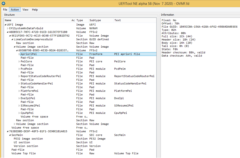
这个函数的作用是找到所有的 PEIM以及Apriori 文件。
/**

  Discover all PEIMs and optional Apriori file in one FV. There is at most one
  Apriori file in one FV.


  @param Private          Pointer to the private data passed in from caller
  @param CoreFileHandle   The instance of PEI_CORE_FV_HANDLE.

**/
VOID
DiscoverPeimsAndOrderWithApriori (
  IN  PEI_CORE_INSTANCE    *Private,
  IN  PEI_CORE_FV_HANDLE   *CoreFileHandle
  )
函数中有一个 DEBUG 输出如下:
  DEBUG ((
    DEBUG_INFO,
    "%a(): Found 0x%x PEI FFS files in the %dth FV\n",
    __FUNCTION__,
    PeimCount,
    Private->CurrentPeimFvCount
));
对应的串口 Log 中有如下字样,就是说在找到了7个 PEIM
DiscoverPeimsAndOrderWithApriori(): Found 0x7 PEI FFS files in the 0th FV
为了更好的观测,加入代码,输出它找到的 PEIM 的 GUID:
      for (Index = 0; Index < PeimCount; Index++) {
        //
        // Make an array of file name GUIDs that matches the FileHandle array so we can convert
        // quickly from file name to file handle
        //
        Status = FvPpi->GetFileInfo (FvPpi, TempFileHandles[Index], &FileInfo);
        ASSERT_EFI_ERROR (Status);
        CopyMem (&TempFileGuid[Index], &FileInfo.FileName, sizeof(EFI_GUID));
		DEBUG ((DEBUG_INFO , "%g\n", FileInfo.FileName));
      }
              //
              // For PEIM driver, Load its entry point
              //
              Status = PeiLoadImage (
                         PeiServices,
                         PeimFileHandle,
                         PEIM_STATE_NOT_DISPATCHED,
                         &EntryPoint,
                         &AuthenticationState
                         );
/**
  Routine to load image file for subsequent execution by LoadFile Ppi.
  If any LoadFile Ppi is not found, the build-in support function for the PE32+/TE
  XIP image format is used.

  @param PeiServices     - An indirect pointer to the EFI_PEI_SERVICES table published by the PEI Foundation
  @param FileHandle      - Pointer to the FFS file header of the image.
  @param PeimState       - The dispatch state of the input PEIM handle.
  @param EntryPoint      - Pointer to entry point of specified image file for output.
  @param AuthenticationState - Pointer to attestation authentication state of image.

  @retval EFI_SUCCESS    - Image is successfully loaded.
  @retval EFI_NOT_FOUND  - Fail to locate necessary PPI
  @retval Others         - Fail to load file.

**/
EFI_STATUS
PeiLoadImage (
  IN     CONST EFI_PEI_SERVICES       **PeiServices,
  IN     EFI_PEI_FILE_HANDLE          FileHandle,
  IN     UINT8                        PeimState,
  OUT    EFI_PHYSICAL_ADDRESS         *EntryPoint,
  OUT    UINT32                       *AuthenticationState
  )
/**
  Loads a PEIM into memory for subsequent execution. If there are compressed
  images or images that need to be relocated into memory for performance reasons,
  this service performs that transformation.

  @param PeiServices      An indirect pointer to the EFI_PEI_SERVICES table published by the PEI Foundation
  @param FileHandle       Pointer to the FFS file header of the image.
  @param ImageAddressArg  Pointer to PE/TE image.
  @param ImageSizeArg     Size of PE/TE image.
  @param EntryPoint       Pointer to entry point of specified image file for output.
  @param AuthenticationState - Pointer to attestation authentication state of image.

  @retval EFI_SUCCESS      Image is successfully loaded.
  @retval EFI_NOT_FOUND    Fail to locate necessary PPI.
  @retval EFI_UNSUPPORTED  Image Machine Type is not supported.
  @retval EFI_WARN_BUFFER_TOO_SMALL
                           There is not enough heap to allocate the requested size.
                           This will not prevent the XIP image from being invoked.

**/
EFI_STATUS
PeiLoadImageLoadImage (
  IN     CONST EFI_PEI_SERVICES       **PeiServices,
  IN     EFI_PEI_FILE_HANDLE          FileHandle,
  OUT    EFI_PHYSICAL_ADDRESS         *ImageAddressArg,  OPTIONAL
  OUT    UINT64                       *ImageSizeArg,     OPTIONAL
  OUT    EFI_PHYSICAL_ADDRESS         *EntryPoint,
  OUT    UINT32                       *AuthenticationState
  )
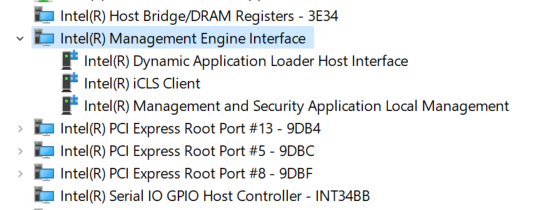
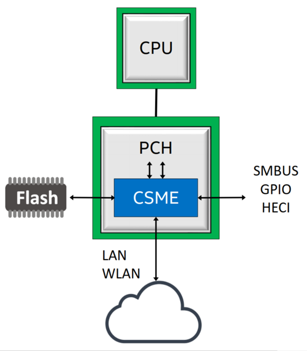
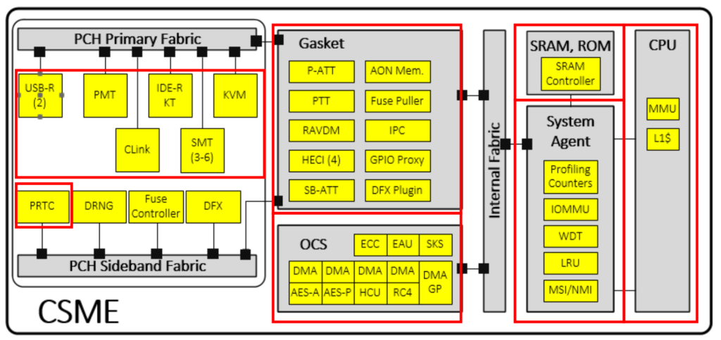
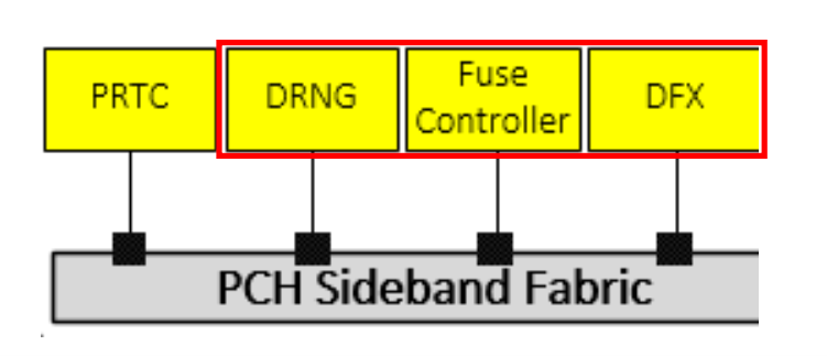
CSME 算是 Intel X86 PC 上最神秘的部分了,本文根据 us-19-Hasarfaty-Behind-The-Scenes-Of-Intel-Security-And-Manageability-Engine 一文写成。讲述内容无法证伪,各位随便听听即可,了解这些能够帮助BIOS 工程师更好的理解一些操作的实现。文章基于 Intel 第八代第九代CPU(Coffee Lake 和 Whiskey Lake)进行描述。