UEFI System Table 中的 ConOut-> OutputString 能够让我们直接在屏幕上输出字符串。这里介绍一种方法,能够让我们截获并且修改这个函数输出的字符串。
首先看一下 System Table 的定义在 \MdePkg\Include\Uefi\UefiSpec.h
///

/// EFI System Table

///

typedef struct {

///

/// The table header for the EFI System Table.

///

EFI_TABLE_HEADER                  Hdr;

///

/// A pointer to a null terminated string that identifies the vendor

/// that produces the system firmware for the platform.

///

CHAR16                            *FirmwareVendor;

///

/// A firmware vendor specific value that identifies the revision

/// of the system firmware for the platform.

///

UINT32                            FirmwareRevision;

///

/// The handle for the active console input device. This handle must support

/// EFI_SIMPLE_TEXT_INPUT_PROTOCOL and EFI_SIMPLE_TEXT_INPUT_EX_PROTOCOL.

///

EFI_HANDLE                        ConsoleInHandle;

///

/// A pointer to the EFI_SIMPLE_TEXT_INPUT_PROTOCOL interface that is

/// associated with ConsoleInHandle.

///

EFI_SIMPLE_TEXT_INPUT_PROTOCOL    *ConIn;

///

/// The handle for the active console output device.

///

EFI_HANDLE                        ConsoleOutHandle;

///

/// A pointer to the EFI_SIMPLE_TEXT_OUTPUT_PROTOCOL interface

/// that is associated with ConsoleOutHandle.

///

EFI_SIMPLE_TEXT_OUTPUT_PROTOCOL   *ConOut;

///

/// The handle for the active standard error console device.

/// This handle must support the EFI_SIMPLE_TEXT_OUTPUT_PROTOCOL.

///

EFI_HANDLE                        StandardErrorHandle;

///

/// A pointer to the EFI_SIMPLE_TEXT_OUTPUT_PROTOCOL interface

/// that is associated with StandardErrorHandle.

///

EFI_SIMPLE_TEXT_OUTPUT_PROTOCOL   *StdErr;

///

/// A pointer to the EFI Runtime Services Table.

///

EFI_RUNTIME_SERVICES              *RuntimeServices;

///

/// A pointer to the EFI Boot Services Table.

///

EFI_BOOT_SERVICES                 *BootServices;

///

/// The number of system configuration tables in the buffer ConfigurationTable.

///

UINTN                             NumberOfTableEntries;

///

/// A pointer to the system configuration tables.

/// The number of entries in the table is NumberOfTableEntries.

///

EFI_CONFIGURATION_TABLE           *ConfigurationTable;

} EFI_SYSTEM_TABLE;
其中的ConOut 是指向 EFI_SIMPLE_TEXT_OUTPUT_PROTOCOL 的指针
具体定义可以在 \MdePkg\Include\Protocol\SimpleTextOut.h 查到
///

/// The SIMPLE_TEXT_OUTPUT protocol is used to control text-based output devices.

/// It is the minimum required protocol for any handle supplied as the ConsoleOut

/// or StandardError device. In addition, the minimum supported text mode of such

/// devices is at least 80 x 25 characters.

///

struct _EFI_SIMPLE_TEXT_OUTPUT_PROTOCOL {

EFI_TEXT_RESET                Reset;

EFI_TEXT_STRING               OutputString;

EFI_TEXT_TEST_STRING          TestString;

EFI_TEXT_QUERY_MODE           QueryMode;

EFI_TEXT_SET_MODE             SetMode;

EFI_TEXT_SET_ATTRIBUTE        SetAttribute;

EFI_TEXT_CLEAR_SCREEN         ClearScreen;

EFI_TEXT_SET_CURSOR_POSITION  SetCursorPosition;

EFI_TEXT_ENABLE_CURSOR        EnableCursor;

///

/// Pointer to SIMPLE_TEXT_OUTPUT_MODE data.

///

EFI_SIMPLE_TEXT_OUTPUT_MODE   *Mode;

};
我们需要的是将 EFI_TEXT_STRING OutputString; 替换为我们自己的函数。
最终的代码如下
#include <Uefi.h>
#include <Library/UefiLib.h>
#include <Library/ShellCEntryLib.h>
extern EFI_BOOT_SERVICES *gBS;
extern EFI_SYSTEM_TABLE *gST;
extern EFI_RUNTIME_SERVICES *gRT;
EFI_SYSTEM_TABLE myST;
EFI_SYSTEM_TABLE *pmyST=&myST;
EFI_SIMPLE_TEXT_OUTPUT_PROTOCOL myConOut;
EFI_STATUS
myOut (
IN EFI_SIMPLE_TEXT_OUTPUT_PROTOCOL *This,
IN CHAR16 *String
)
{
//Just a experiment, add a String to the output
CHAR16 R[40]=L"LAB-Z:";
StrCat(R,String);
gST->ConOut->OutputString(This,R);
return EFI_SUCCESS;
}
int
EFIAPI
main (
IN int Argc,
IN CHAR16 **Argv
)
{
//Create a fake EFI_SYSTEM_TABLE named myST
memcpy(&myST,gST,sizeof(EFI_SYSTEM_TABLE));
//Test this EFI_SYSTEM_TABLE
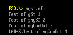
gST->ConOut->OutputString( gST->ConOut,L"Test of gSt 1\n\r");
pmyST->ConOut->OutputString(pmyST->ConOut,L"Test of pmyST 2\n\r");
//Create a fake EFI_SIMPLE_TEXT_OUTPUT_PROTOCOL
memcpy(&myConOut,gST->ConOut,sizeof(EFI_SIMPLE_TEXT_OUTPUT_PROTOCOL));
//Test the fake ConOut
pmyST->ConOut=&myConOut;
//If we use pmyST->ConOut it will be an error
pmyST->ConOut->OutputString(gST->ConOut,L"Test of myConOut 3\n\r");
//Replace OutputString function with our function
pmyST->ConOut->OutputString=&myOut;
pmyST->ConOut->OutputString(gST->ConOut,L"Test of myConOut 4\n\r");
return EFI_SUCCESS;
}
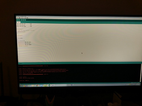
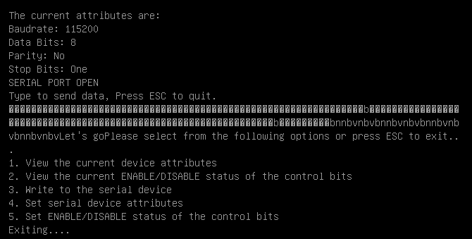
运行结果
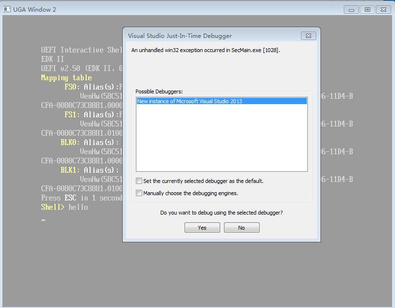
特别需要注意的地方,如果我们写成
pmyST->ConOut->OutputString(pmyST ->ConOut,L”Test of myConOut 3\n\r”);
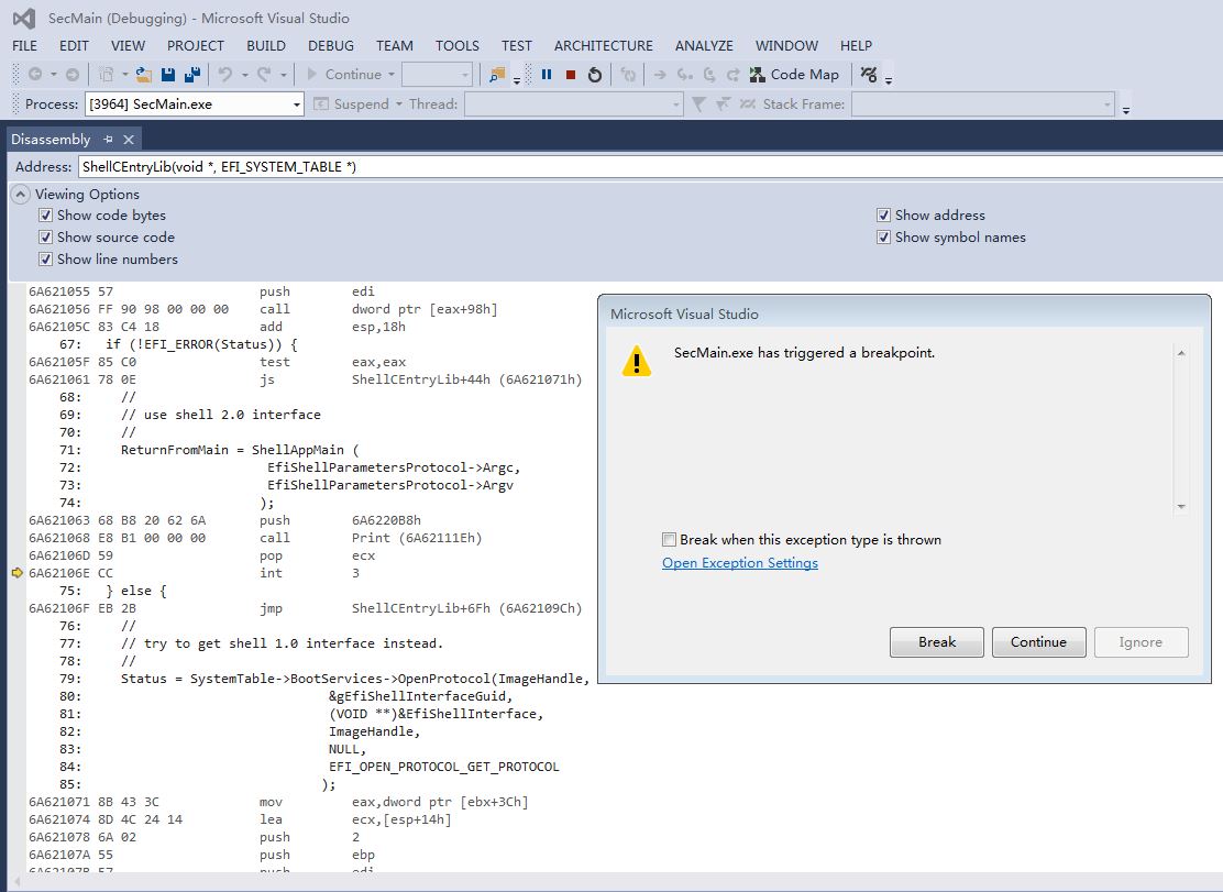
那么会碰到下面这个错误
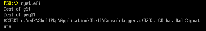
产生问题的代码在 \ShellPkg\Application\Shell\ConsoleLogger.c 中,看起来是向 Handle 安装另外一个 Protocol的时候出现报错信息。
  Status = gBS->InstallProtocolInterface(&gImageHandle, &gEfiSimpleTextOutProtocolGuid, EFI_NATIVE_INTERFACE, (VOID*)&((*ConsoleInfo)->OurConOut));
  if (EFI_ERROR(Status)) {
    SHELL_FREE_NON_NULL((*ConsoleInfo)->Buffer);
    SHELL_FREE_NON_NULL((*ConsoleInfo)->Attributes);
    SHELL_FREE_NON_NULL((*ConsoleInfo));
    *ConsoleInfo = NULL;
    return (Status);
  }

  gST->ConsoleOutHandle = gImageHandle;
  gST->ConOut           = &(*ConsoleInfo)->OurConOut;

  return (Status);
完整的代码下载:
MySt
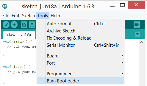
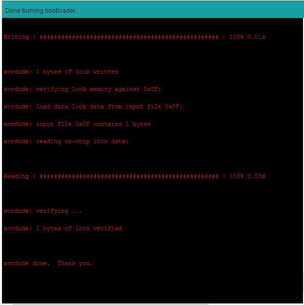
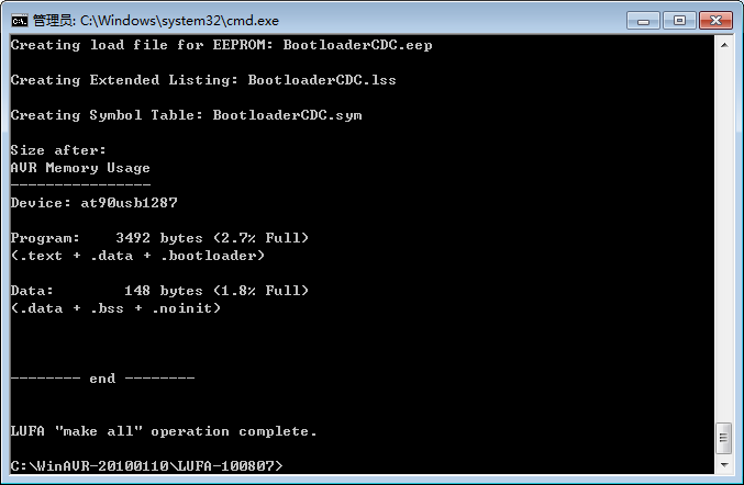
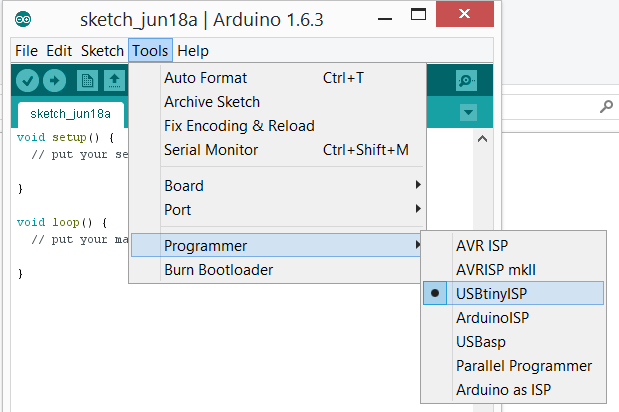 3.Tools->BurnBootloader 直接烧写 328P 的Bootloader