最近网上发现一个 Arduino 管脚的分布图,清晰详细,在 https://github.com/Bouni/Arduino-Pinout
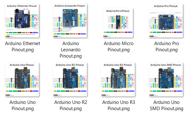
每一幅在3000×300以上,还特别提供矢量图
我在 Baidu 盘上放了一份有兴趣的朋友可以下载
链接: http://pan.baidu.com/s/1milKCS4 密码: sbhw
最近网上发现一个 Arduino 管脚的分布图,清晰详细,在 https://github.com/Bouni/Arduino-Pinout
每一幅在3000×300以上,还特别提供矢量图
我在 Baidu 盘上放了一份有兴趣的朋友可以下载
链接: http://pan.baidu.com/s/1milKCS4 密码: sbhw
这次介绍一个通过驱动程序旋转屏幕的项目,地址是https://github.com/apop2/GopRotate 。项目的简介是“A EDK2 Package that supplies a UEFI driver that will bind on top of Graphics Output Devices and rotate any BLT operations by 0, 90, 180 or 270 degrees.”。
本文并不打算做原理上的分析,只是介绍如何编译和实验。
实验环境是 UDK2014
1.在 C:\EDK\Nt32Pkg\Nt32Pkg.dsc 文件的 [Components] 段中添加下面的内容
  MdeModulePkg/Application/VariableInfo/VariableInfo.inf
  MdeModulePkg/Universal/PlatformDriOverrideDxe/PlatformDriOverrideDxe.inf
##LABZDebug_Start
  GopRotatePkg/GopRotate/GopRotate.inf
##LABZDebug_End
###################################################################################################
#
# BuildOptions Section - Define the module specific tool chain flags that should be used as
#                        the default flags for a module. These flags are appended to any
2.将 GopRotatePkg 目录拷贝到你UDK 的根目录下 例如: C:\EDK\
3.使用 Build 命令编译 NT32
4.使用 build run 运行模拟器
至此,驱动程序已经编译完成。下面要编译使用这个驱动的 Application。
5.将GopRot 按照一个普通的Application编译
编译完成后可以进行实验了。
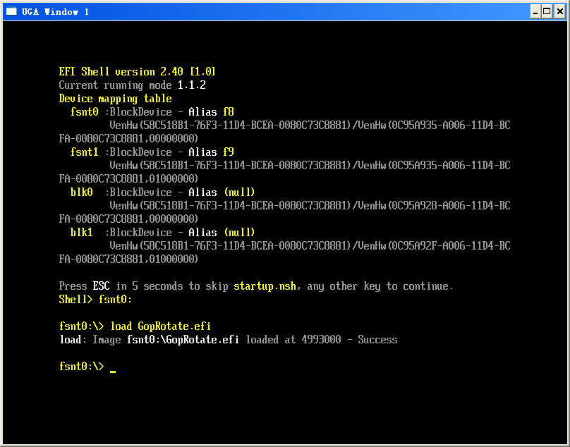
6.使用 load goprotate.efi 加载驱动
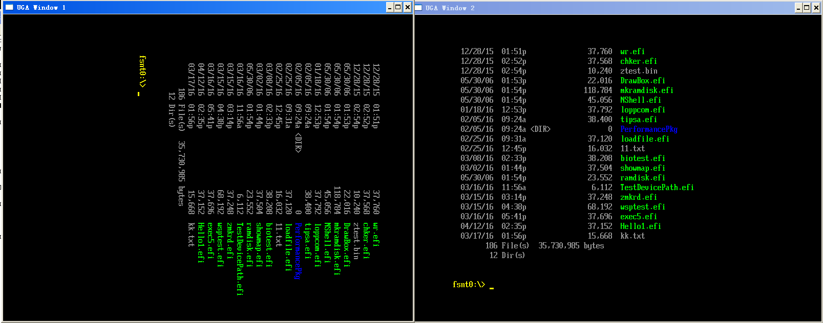
7.输入 goprot.efi 2 进行测试。
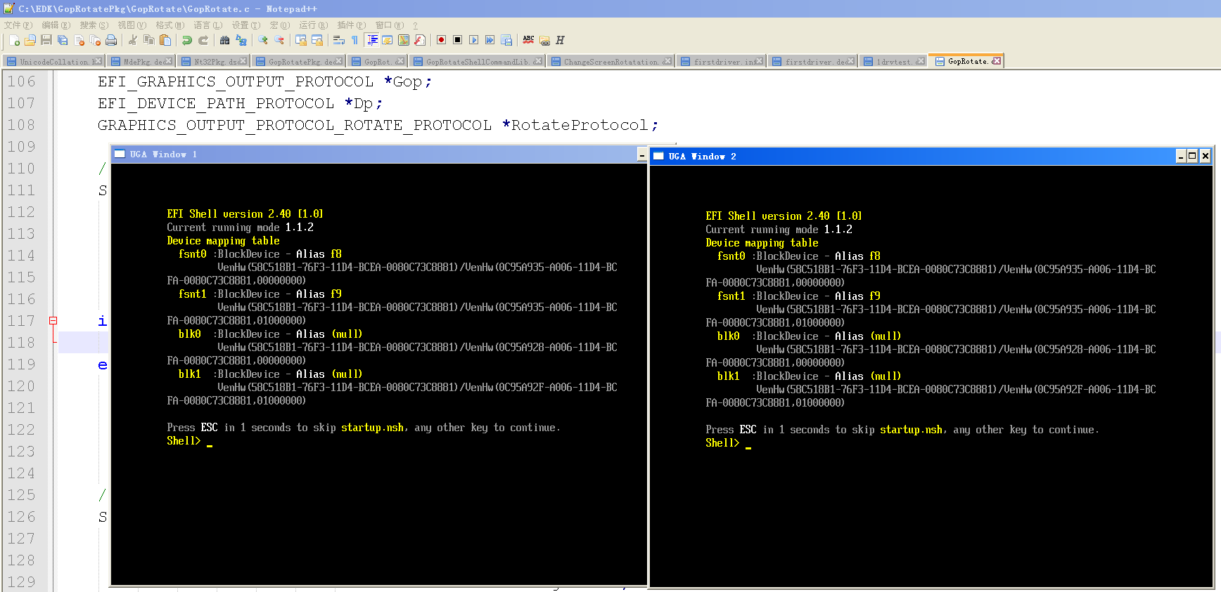
运行之前的屏幕是这样的:
运行之后屏幕就变成这样了
完整的代码下载
前面提到的驱动项目完整代码
GopRotatePkg
调用驱动的应用程序代码
GopRot
一个标准的 Arduino Uno上面有两个可以编程的IC,一个是负责USB 转串口的ATmega16U2,一个主控芯片ATmega328P,下图红色标记的就是16u2,绿色标记的是 328P.
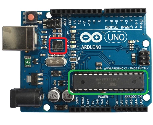
然后对应的有三种Firmware: 16U2 中有一个, 328P 中有两个。16u2的负责USB转串口;328P的一个Firmware是BootLoader,从功能上说主要是负责把 16u2收到串口数据刷新到328P 上;328P中的另外一个 Firmware 就是我们平常写的程序,编译之后生成的,用来完成我们期望的功能。
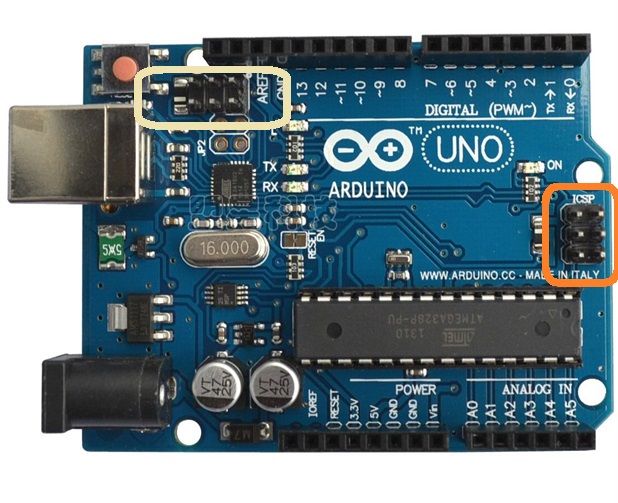
一般情况下,如果想更新16u2,需要额外的设备,比如 USB IPS ; 我们IDE只能更新328P 中的程序部分.328P 的BootLoader也是需要额外的设备来进行更新的。更新 16u2使用下图左上角框住部分的排针,更新 328P 使用下图中间橘色框图中指出的引脚。
16u2的Firmware 可以在类似 \arduino-1.6.3\hardware\arduino\avr\firmwares\atmegaxxu2\arduino-usbserial 的路径中找到
328P Bootloader 的Firmware 可以在\arduino-1.6.3\hardware\arduino\avr\bootloaders\atmega 的路径中找到。
查看UEFI下的大小写转换函数的时候,偶然发现了EFI_UNICODE_COLLATION_PROTOCOL【参考1】提供了几个有意思的函数。
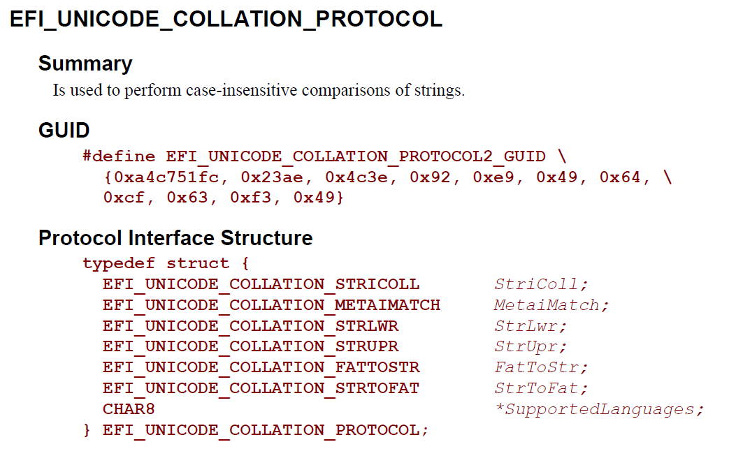
具体的头文件定义在 \MdePkg\Include\Protocol\UnicodeCollation.h
///
/// The EFI_UNICODE_COLLATION_PROTOCOL is used to perform case-insensitive
/// comparisons of strings.
///
struct _EFI_UNICODE_COLLATION_PROTOCOL {
  EFI_UNICODE_COLLATION_STRICOLL    StriColl;
  EFI_UNICODE_COLLATION_METAIMATCH  MetaiMatch;
  EFI_UNICODE_COLLATION_STRLWR      StrLwr;
  EFI_UNICODE_COLLATION_STRUPR      StrUpr;

  //
  // for supporting fat volumes
  //
  EFI_UNICODE_COLLATION_FATTOSTR    FatToStr;
  EFI_UNICODE_COLLATION_STRTOFAT    StrToFat;

  ///
  /// A Null-terminated ASCII string array that contains one or more language codes.
  /// When this field is used for UnicodeCollation2, it is specified in RFC 4646 format.
  /// When it is used for UnicodeCollation, it is specified in ISO 639-2 format.
  ///
  CHAR8                             *SupportedLanguages;
};
根据介绍,大概的介绍一些功能(如果你发现有错误,欢迎eMail指出)
EFI_UNICODE_COLLATION_STRICOLL StriColl; //大小写不敏感的比较函数
EFI_UNICODE_COLLATION_METAIMATCH MetaiMatch; //正则表达式匹配
EFI_UNICODE_COLLATION_STRLWR StrLwr; //字符串转小写
EFI_UNICODE_COLLATION_STRUPR StrUpr; //字符串转大写
EFI_UNICODE_COLLATION_FATTOSTR FatToStr; //8.3格式的OEM定义字符文件名转String
EFI_UNICODE_COLLATION_STRTOFAT StrToFat; //String转8.3格式的OEM定义字符
CHAR8 *SupportedLanguages; //列出当前系统支持的语言代码
之后,根据上面的介绍,编写一个测试例子:
#include  <Uefi.h>
#include  <Library/UefiLib.h>
#include  <Library/ShellCEntryLib.h>

#include <Protocol/UnicodeCollation.h>

extern EFI_BOOT_SERVICES         *gBS;
extern EFI_SYSTEM_TABLE			 *gST;
extern EFI_RUNTIME_SERVICES 	 *gRT;

int
EFIAPI
main (
  IN int Argc,
  IN CHAR16 **Argv
  )
{
	EFI_STATUS	Status;
	EFI_UNICODE_COLLATION_PROTOCOL *mUnicodeCollation;
	CHAR16	*TestStr=L"wWw.LaB-z.cOm";
	CHAR16  *Pattern1=L"w*";
	CHAR16  *Pattern2=L"*z.c*";
	CHAR16  *Pattern3=L"c*";

	Status = gBS->LocateProtocol(
				&gEfiUnicodeCollation2ProtocolGuid,
				NULL,
				&mUnicodeCollation);
    if (EFI_ERROR (Status)) {
      Print(L"Can't Locate Protocol\n");
      return Status;
    }

	mUnicodeCollation->StrLwr(mUnicodeCollation,TestStr);
	Print(L"%s\n",TestStr);

	mUnicodeCollation->StrUpr(mUnicodeCollation,TestStr);
	Print(L"%s\n",TestStr);

	Print(L"%d\n",(mUnicodeCollation->
					MetaiMatch(mUnicodeCollation,
					   TestStr,
					   Pattern1)));

	Print(L"%d\n",(mUnicodeCollation->
					MetaiMatch(mUnicodeCollation,
					   TestStr,
					   Pattern2)));

	Print(L"%d\n",(mUnicodeCollation->
					MetaiMatch(mUnicodeCollation,
					   TestStr,
					   Pattern3)));
  return EFI_SUCCESS;
}
运行结果:
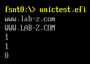
其中测试了大小写转换不必细说,多说两句关于正则表达式的用法:
	CHAR16	*TestStr=L"wWw.LaB-z.cOm";
	CHAR16  *Pattern1=L"w*";
	CHAR16  *Pattern2=L"*z.c*";
	CHAR16  *Pattern3=L"c*";
其中 “*” 表示匹配一个或者任意多个字符, Pattern1 表示的是“以w开头的字符串”;Pattern2 表示的是“中间含有 z.c 字符的字符串”;Pattern3 表示的是“以c开头的字符串”。最终运行结果如下:
完整的代码下载:
UnicTest
参考:
1. UEFI 2.4 P592
Base64编码出现的背景【参考1】:电子邮件的传输需要把原始内容编码为可见的ASCII来进行传输,很早之前出现的电子邮件编码规则兼容性不太好,比如没有考虑邮件的多种内容的问题,还有对文件音频视频附件之类兼容不好。因此,提出来新的编码,这种新的编码格式编解码很简单,同时编码后的内容只比编码之前大33%,这就是Base64。
这里是来自网上【参考2】的一份 Arduino base64库,下面简单介绍一下用法:
int base64_encode(char *output, char *input, int inputLen); 对字符串进行base64编码
int base64_decode(char *output, char *input, int inputLen); 对Base64字符串进行b解码
int base64_enc_len(int inputLen); “预测”Base64编码后的字符串长度
int base64_dec_len(char *input, int inputLen); “预测”Base64编码字符串解码后的字符串长度
下面是一个完整的例子【参考2】:
#include <Base64.h>

/*
 Base64 Encode/Decode example

 Encodes the text "Hello world" to "SGVsbG8gd29ybGQA" and decodes "Zm9vYmFy" to "foobar"

 Created 29 April 2015
 by Nathan Friedly - http://nfriedly.com/

 This example code is in the public domain.

 */


void setup()
{
  // start serial port at 9600 bps:
  Serial.begin(9600);
  while (!Serial) {
    ; // wait for serial port to connect. Needed for Leonardo only
  }

  Serial.println("Base64 example");


  // encoding
  char input[] = "Hello world";
  int inputLen = sizeof(input);

  int encodedLen = base64_enc_len(inputLen);
  char encoded[encodedLen];

  Serial.print(input); Serial.print(" = ");

  // note input is consumed in this step: it will be empty afterwards
  base64_encode(encoded, input, inputLen);

  Serial.println(encoded);


  // decoding
  char input2[] = "Zm9vYmFy";
  int input2Len = sizeof(input2);

  int decodedLen = base64_dec_len(input2, input2Len);
  char decoded[decodedLen];

  base64_decode(decoded, input2, input2Len);

  Serial.print(input2); Serial.print(" = "); Serial.println(decoded);
}


void loop()
{

}
运行结果:
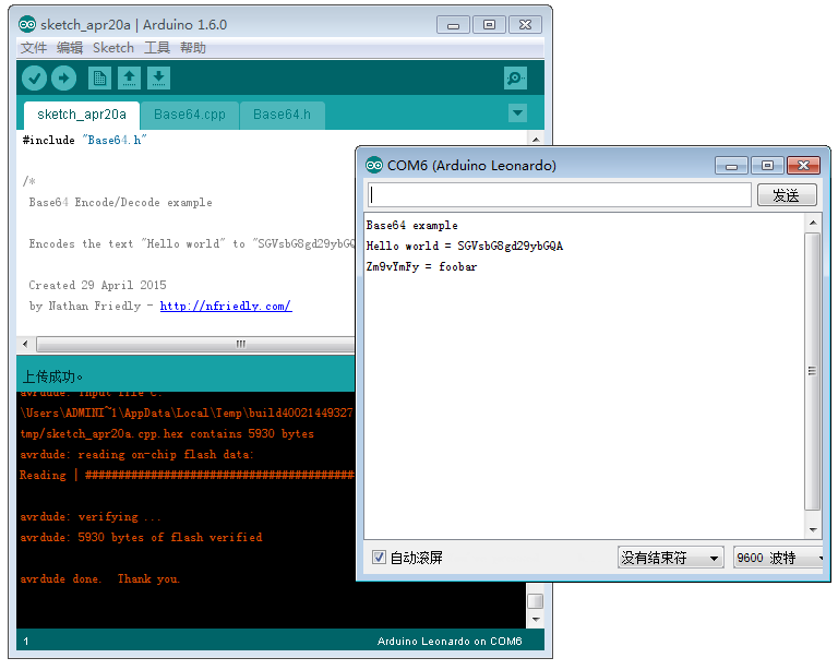
这里【参考4】,提供了一个在线版的Base64编解码工具,可以用来检查结果是否正确。
完整的代码下载:
sketch_apr20a
最后,之前我还介绍过MD5的 Arduino 库【参考3】,有兴趣的朋友也可以研究一下。
参考:
1. http://www.faqs.org/rfcs/rfc2045.html
2. https://github.com/adamvr/arduino-base64 库下载
arduino-base64-master
3. http://www.lab-z.com/arduinomd5/ Arduino 的MD5库
4. http://www1.tc711.com/tool/BASE64.htm 在线编码解码
前面【参考1】提到了 StartImage 加载 CLib 编写Application 出错的原因,这篇文章介绍如何解决这个问题。
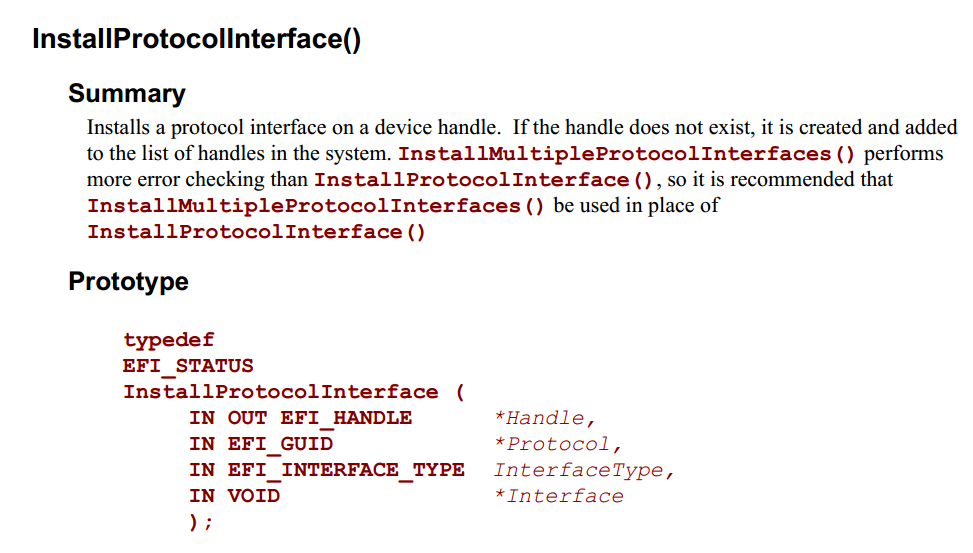
根据原因来看是因为找不到提供 Parameters 的Protocol,那么我们在调用之前给被加载的Application 装上需要的Protocol即可。安装 Protocol 需要用到 InstallProtocollInterface,具体定义如下【参考2】:
欲安装的 Protocol 实例则是从加载程序(Exec6)上面取下来的。
没有多少人愿意看大篇幅的代码,我这里列下最关键的部分:
首先,取出当前的 Shell Interface, 不同的环境下还可以使用 Shell Parameter Protocol , NT32 环境下只支持前者
//如果你在实体机上发现有问题,那么可以考虑这段代码的问题
  Status = gBS->OpenProtocol(gImageHandle,
                             &gEfiShellInterfaceGuid,
                             (VOID **)&EfiShellInterface,
                             gImageHandle,
                             NULL,
                             EFI_OPEN_PROTOCOL_GET_PROTOCOL
                            );
  if (EFI_ERROR(Status)) {
	Print(L"Shell Parameters Protocol not Found!\r\n",Status);
    return (Status);
  }
//之后,将取下来的 Protocol 安装给被加载的 Application
  Status = gBS->InstallProtocolInterface (
            &NewHandle,
            &gEfiShellInterfaceGuid,
            EFI_NATIVE_INTERFACE,
            EfiShellInterface
           );
  if (EFI_ERROR(Status)) {
	Print(L"Protocol Interface Installed fail!\r\n",Status);
	return (Status);
  }
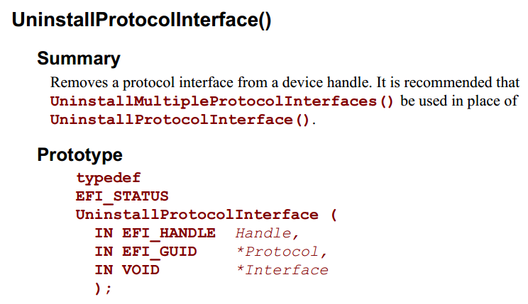
最后,安装之后不能忘记 Uninstall,还要调用一下,特别注意第一个参数传递的不是指针。
运行结果,可以看出 Hello1和 Hello2都可以被正常加载运行:
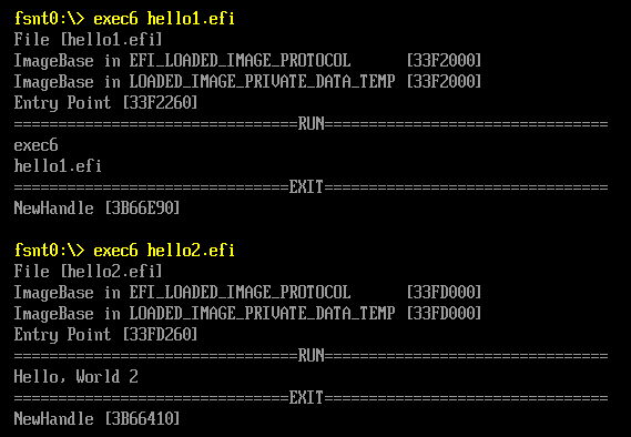
看到这里,这篇文章就可以结束了,下面列出 Exec6 的代码:
#include  <Uefi.h>
#include  <Library/UefiLib.h>
#include  <Library/ShellCEntryLib.h>

#include  <stdio.h>
#include  <stdlib.h>
#include  <wchar.h>

#include <Protocol/EfiShell.h>
#include <Library/ShellLib.h>

extern EFI_BOOT_SERVICES           	 *gBS;
extern EFI_SYSTEM_TABLE				 *gST;
extern EFI_RUNTIME_SERVICES 		 *gRT;

extern EFI_SHELL_PROTOCOL            *gEfiShellProtocol;
extern EFI_SHELL_ENVIRONMENT2 		 *mEfiShellEnvironment2;

extern EFI_HANDLE					 gImageHandle;

typedef struct {
  UINTN                       Signature;
  /// Image handle
  EFI_HANDLE                  Handle;
  /// Image type
  UINTN                       Type;
  /// If entrypoint has been called
  BOOLEAN                     Started;
  /// The image's entry point
  EFI_IMAGE_ENTRY_POINT       EntryPoint;
  /// loaded image protocol
  EFI_LOADED_IMAGE_PROTOCOL   Info;
  /// Location in memory
  EFI_PHYSICAL_ADDRESS        ImageBasePage;
} LOADED_IMAGE_PRIVATE_DATA_TEMP;

#define _CR(Record, TYPE, Field)  ((TYPE *) ((CHAR8 *) (Record) - (CHAR8 *) &(((TYPE *) 0)->Field)))

#define LOADED_IMAGE_PRIVATE_DATA_FROM_THIS(a) \
          _CR(a, LOADED_IMAGE_PRIVATE_DATA_TEMP, Info)

/**
  GET  DEVICEPATH
**/
EFI_DEVICE_PATH_PROTOCOL *
EFIAPI
ShellGetDevicePath (
  IN CHAR16                     * CONST DeviceName OPTIONAL
  )
{
  //
  // Check for UEFI Shell 2.0 protocols
  //
  if (gEfiShellProtocol != NULL) {
    return (gEfiShellProtocol->GetDevicePathFromFilePath(DeviceName));
  }

  //
  // Check for EFI shell
  //
  if (mEfiShellEnvironment2 != NULL) {
    return (mEfiShellEnvironment2->NameToPath(DeviceName));
  }

  return (NULL);
}

int
EFIAPI
main (
  IN int Argc,
  IN CHAR16 **Argv
  )
{
  EFI_DEVICE_PATH_PROTOCOL *DevicePath;
  EFI_HANDLE	NewHandle;
  EFI_STATUS	Status;
  LOADED_IMAGE_PRIVATE_DATA_TEMP      *private = NULL;
  UINTN			ExitDataSizePtr;
  EFI_LOADED_IMAGE_PROTOCOL	*ImageInfo = NULL;
    EFI_SHELL_INTERFACE           *EfiShellInterface=NULL;

  if (Argc!=2) {
		Print(L"Usage: Exec4 FileName\n");
		return EFI_SUCCESS;
  }

  Print(L"File [%s]\n",Argv[1]);

  DevicePath=ShellGetDevicePath(Argv[1]);

  //
  // Load the image with:
  // FALSE - not from boot manager and NULL, 0 being not already in memory
  //
  Status = gBS->LoadImage(
    FALSE,
    gImageHandle,
    DevicePath,
    NULL,
    0,
    &NewHandle);

  if (EFI_ERROR(Status)) {
    if (NewHandle != NULL) {
      gBS->UnloadImage(NewHandle);
    }
	Print(L"Error during LoadImage [%X]\n",Status);
    return (Status);
  }

  Status = gBS -> HandleProtocol (
						NewHandle,
						&gEfiLoadedImageProtocolGuid,
						&ImageInfo
						);

  private = LOADED_IMAGE_PRIVATE_DATA_FROM_THIS(ImageInfo);

  Print(L"ImageBase in EFI_LOADED_IMAGE_PROTOCOL      [%lX]\n",ImageInfo->ImageBase);
  Print(L"ImageBase in LOADED_IMAGE_PRIVATE_DATA_TEMP [%lX]\n",private->ImageBasePage);
  Print(L"Entry Point [%lX]\n",private->EntryPoint);

  Status = gBS->OpenProtocol(gImageHandle,
                             &gEfiShellInterfaceGuid,
                             (VOID **)&EfiShellInterface,
                             gImageHandle,
                             NULL,
                             EFI_OPEN_PROTOCOL_GET_PROTOCOL
                            );
  if (EFI_ERROR(Status)) {
	Print(L"Shell Parameters Protocol not Found!\r\n",Status);
    return (Status);
  }

  Status = gBS->InstallProtocolInterface (
            &NewHandle,
            &gEfiShellInterfaceGuid,
            EFI_NATIVE_INTERFACE,
            EfiShellInterface
           );
  if (EFI_ERROR(Status)) {
	Print(L"Protocol Interface Installed fail!\r\n",Status);
	return (Status);
  }

  Print(L"================================RUN================================\r\n",Status);

  //
  // now start the image, passing up exit data if the caller requested it
  //
  Status = gBS->StartImage(
                     NewHandle,
                     &ExitDataSizePtr,
                     NULL
              );
  if (EFI_ERROR(Status)) {
    if (NewHandle != NULL) {
      gBS->UnloadImage(NewHandle);
    }
	Print(L"Error during StartImage [%X]\r\n",Status);
    return (Status);
  }

  Print(L"===============================EXIT================================\r\n",Status);

  Status = gBS->UninstallProtocolInterface (
            NewHandle,
            &gEfiShellInterfaceGuid,
            EfiShellInterface
           );
  if (EFI_ERROR(Status)) {
	Print(L"Protocol Interface Uninstalled fail!\r\n",Status);
	return (Status);
  }

  gBS->UnloadImage (NewHandle);

  Print(L"NewHandle [%lX]\n",NewHandle);

  return EFI_SUCCESS;
}
完整代码下载:
exec6
至此,终于回答了 StartImage 执行Application 的问题,如果你发现本文有任何问题欢迎给我留言,或者你有什么其他问题,同样可以给我发 e-Mail。
就是这样。
参考:
1. http://www.lab-z.com/stu85/ StartImage CLib
2. Uefi Spec 2.4 P153
之前文章中提到过,用LoadImage和StartImage无法加载CLIB build出来的 Application。这次认真研究一下这个问题。
首先,准备实验的材料: 两个简单的小程序 Hello1 和 Hello2 。前者是 CLIB 编出来的,后者是普通的EFI 程序。此外还有一个加载器程序 exec4.efi 。
1. 单独执行编译出来的 Hello1.efi 和Hello2.efi都没问题。实验 exec4 ,加载 hello1.efi 会出错,虚拟机会重启到 Setup中,加载 hello2.efi 正常;
2. 对 Hello1 进行分析,分析的方法是加入【参考1】提到的那种按键Pause。
2.1 在Build\NT32IA32\DEBUG_MYTOOLS\IA32\AppPkg\Applications\Hello1\Hello1\Makefile文件中可以看到,入口定义:
IMAGE_ENTRY_POINT = _ModuleEntryPoint
2.2 我们再根据编译过程生成的MAP文件,确定 _ModuleEntryPoint 是在 ApplicationEntryPoint.c 中。同样【参考2】可以给我们提供很多经验,相比普通的EFI程序,增加的CLib只是在整个架构中插入了多函数,并不会改变整体的架构。
/**
  Entry point to UEFI Application.

  This function is the entry point for a UEFI Application. This function must call
  ProcessLibraryConstructorList(), ProcessModuleEntryPointList(), and ProcessLibraryDestructorList().
  The return value from ProcessModuleEntryPointList() is returned.
  If _gUefiDriverRevision is not zero and SystemTable->Hdr.Revision is less than _gUefiDriverRevison,
  then return EFI_INCOMPATIBLE_VERSION.

  @param  ImageHandle                The image handle of the UEFI Application.
  @param  SystemTable                A pointer to the EFI System Table.

  @retval  EFI_SUCCESS               The UEFI Application exited normally.
  @retval  EFI_INCOMPATIBLE_VERSION  _gUefiDriverRevision is greater than SystemTable->Hdr.Revision.
  @retval  Other                     Return value from ProcessModuleEntryPointList().

**/
EFI_STATUS
EFIAPI
_ModuleEntryPoint (
  IN EFI_HANDLE        ImageHandle,
  IN EFI_SYSTEM_TABLE  *SystemTable
  )
{
  EFI_STATUS                 Status;

  if (_gUefiDriverRevision != 0) {
    //
    // Make sure that the EFI/UEFI spec revision of the platform is >= EFI/UEFI spec revision of the application.
    //
    if (SystemTable->Hdr.Revision < _gUefiDriverRevision) {
      return EFI_INCOMPATIBLE_VERSION;
    }
  }

  //
  // Call constructor for all libraries.
  //
  ProcessLibraryConstructorList (ImageHandle, SystemTable);

  //
  // Call the module's entry point
  //
  Status = ProcessModuleEntryPointList (ImageHandle, SystemTable);

  //
  // Process destructor for all libraries.
  //
  ProcessLibraryDestructorList (ImageHandle, SystemTable);

  //
  // Return the return status code from the driver entry point
  //
  return Status;
}
首先追到的是 ProcessLibraryConstructorList 我们在其中插入Debug信息。特别注意,插入的位置在 \Build\NT32IA32\DEBUG_MYTOOLS\IA32\AppPkg\Applications\Hello1\Hello1\DEBUG\AutoGen.c
因为这个文件是编译过程中生成的,所以我们不可以重新 Build AppPkg,而要在目录中(\Build\NT32IA32\DEBUG_MYTOOLS\IA32\AppPkg\Applications\Hello1\Hello1\) 直接运行 NMake来编译;
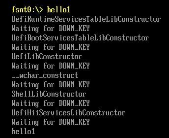
2.3 插入Debug信息后,NMAKE 编译通过,直接运行 Hello1.efi 一次,确保没问题,再用 exec4 加载 hello1.efi 。同样有错误,这说明问题不是发生在ProcessLibraryConstructorList 中;下面是插入后的代码式样:
VOID
EFIAPI
ProcessLibraryConstructorList (
  IN EFI_HANDLE        ImageHandle,
  IN EFI_SYSTEM_TABLE  *SystemTable
  )
{
  EFI_STATUS  Status;
  EFI_INPUT_KEY	Key;

  SystemTable->ConOut->OutputString(SystemTable->ConOut,L"UefiRuntimeServicesTableLibConstructor\n\r");
  Key.ScanCode=SCAN_NULL;
  while (SCAN_UP!=Key.ScanCode)
  {Status= SystemTable -> ConIn -> ReadKeyStroke(SystemTable->ConIn,&Key);}
  SystemTable->ConOut->OutputString(SystemTable->ConOut,L"Waiting for DOWN_KEY\n\r");
  Key.ScanCode=SCAN_NULL;
  while (SCAN_DOWN!=Key.ScanCode)
  {Status= SystemTable -> ConIn -> ReadKeyStroke(SystemTable->ConIn,&Key);}

  Status = UefiRuntimeServicesTableLibConstructor (ImageHandle, SystemTable);
  ASSERT_EFI_ERROR (Status);


  SystemTable->ConOut->OutputString(SystemTable->ConOut,L"UefiBootServicesTableLibConstructor\n\r");
  Key.ScanCode=SCAN_NULL;
  while (SCAN_UP!=Key.ScanCode)
  {Status= SystemTable -> ConIn -> ReadKeyStroke(SystemTable->ConIn,&Key);}
  SystemTable->ConOut->OutputString(SystemTable->ConOut,L"Waiting for DOWN_KEY\n\r");
  Key.ScanCode=SCAN_NULL;
  while (SCAN_DOWN!=Key.ScanCode)
  {Status= SystemTable -> ConIn -> ReadKeyStroke(SystemTable->ConIn,&Key);}

  Status = UefiBootServicesTableLibConstructor (ImageHandle, SystemTable);
  ASSERT_EFI_ERROR (Status);


  SystemTable->ConOut->OutputString(SystemTable->ConOut,L"UefiLibConstructor\n\r");
  Key.ScanCode=SCAN_NULL;
  while (SCAN_UP!=Key.ScanCode)
  {Status= SystemTable -> ConIn -> ReadKeyStroke(SystemTable->ConIn,&Key);}
  SystemTable->ConOut->OutputString(SystemTable->ConOut,L"Waiting for DOWN_KEY\n\r");
  Key.ScanCode=SCAN_NULL;
  while (SCAN_DOWN!=Key.ScanCode)
  {Status= SystemTable -> ConIn -> ReadKeyStroke(SystemTable->ConIn,&Key);}

  Status = UefiLibConstructor (ImageHandle, SystemTable);
  ASSERT_EFI_ERROR (Status);


  SystemTable->ConOut->OutputString(SystemTable->ConOut,L"__wchar_construct\n\r");
  Key.ScanCode=SCAN_NULL;
  while (SCAN_UP!=Key.ScanCode)
  {Status= SystemTable -> ConIn -> ReadKeyStroke(SystemTable->ConIn,&Key);}
  SystemTable->ConOut->OutputString(SystemTable->ConOut,L"Waiting for DOWN_KEY\n\r");
  Key.ScanCode=SCAN_NULL;
  while (SCAN_DOWN!=Key.ScanCode)
  {Status= SystemTable -> ConIn -> ReadKeyStroke(SystemTable->ConIn,&Key);}

  Status = __wchar_construct (ImageHandle, SystemTable);
  ASSERT_EFI_ERROR (Status);


  SystemTable->ConOut->OutputString(SystemTable->ConOut,L"ShellLibConstructor \n\r");
  Key.ScanCode=SCAN_NULL;
  while (SCAN_UP!=Key.ScanCode)
  {Status= SystemTable -> ConIn -> ReadKeyStroke(SystemTable->ConIn,&Key);}
  SystemTable->ConOut->OutputString(SystemTable->ConOut,L"Waiting for DOWN_KEY\n\r");
  Key.ScanCode=SCAN_NULL;
  while (SCAN_DOWN!=Key.ScanCode)
  {Status= SystemTable -> ConIn -> ReadKeyStroke(SystemTable->ConIn,&Key);}

  Status = ShellLibConstructor (ImageHandle, SystemTable);
  ASSERT_EFI_ERROR (Status);


  SystemTable->ConOut->OutputString(SystemTable->ConOut,L"UefiHiiServicesLibConstructor  \n\r");
  Key.ScanCode=SCAN_NULL;
  while (SCAN_UP!=Key.ScanCode)
  {Status= SystemTable -> ConIn -> ReadKeyStroke(SystemTable->ConIn,&Key);}
  SystemTable->ConOut->OutputString(SystemTable->ConOut,L"Waiting for DOWN_KEY\n\r");
  Key.ScanCode=SCAN_NULL;
  while (SCAN_DOWN!=Key.ScanCode)
  {Status= SystemTable -> ConIn -> ReadKeyStroke(SystemTable->ConIn,&Key);}
  Status = UefiHiiServicesLibConstructor (ImageHandle, SystemTable);
  ASSERT_EFI_ERROR (Status);

}
直接运行程序会不断暂停等待按键才继续:
2.4 接下来在ProcessModuleEntryPointList中像上面一样插入Debug,
  //
  // Call the module's entry point
  //
  Status = ProcessModuleEntryPointList (ImageHandle, SystemTable);


EFI_STATUS
EFIAPI
ProcessModuleEntryPointList (
  IN EFI_HANDLE        ImageHandle,
  IN EFI_SYSTEM_TABLE  *SystemTable
  )

{
  EFI_STATUS  Status;
  EFI_INPUT_KEY	Key;

  SystemTable->ConOut->OutputString(SystemTable->ConOut,L"ShellCEntryLib  \n\r");
  Key.ScanCode=SCAN_NULL;
  while (SCAN_UP!=Key.ScanCode)
  {Status= SystemTable -> ConIn -> ReadKeyStroke(SystemTable->ConIn,&Key);}
  SystemTable->ConOut->OutputString(SystemTable->ConOut,L"Waiting for DOWN_KEY\n\r");
  Key.ScanCode=SCAN_NULL;
  while (SCAN_DOWN!=Key.ScanCode)
  {Status= SystemTable -> ConIn -> ReadKeyStroke(SystemTable->ConIn,&Key);}
  Status=ShellCEntryLib (ImageHandle, SystemTable);

  SystemTable->ConOut->OutputString(SystemTable->ConOut,L"ShellCEntryLib Exit \n\r");
  Key.ScanCode=SCAN_NULL;
  while (SCAN_UP!=Key.ScanCode)
  {Status= SystemTable -> ConIn -> ReadKeyStroke(SystemTable->ConIn,&Key);}
  SystemTable->ConOut->OutputString(SystemTable->ConOut,L"Waiting for DOWN_KEY\n\r");
  Key.ScanCode=SCAN_NULL;
  while (SCAN_DOWN!=Key.ScanCode)
  {Status= SystemTable -> ConIn -> ReadKeyStroke(SystemTable->ConIn,&Key);}
  return EFI_SUCCESS;
}
再次实验 Exec4 加载发现,现象消失了。仔细琢磨一下,应该是我最后 return EFI_SUCCESS 导致的。所以问题就应该发生在进入 ShellCEntryLib 那里。
2.5 继续调试直接在 ShellCEntryLib 加入 Debug 信息
/**
  UEFI entry point for an application that will in turn call the
  ShellAppMain function which has parameters similar to a standard C
  main function.

  An application that uses UefiShellCEntryLib must have a ShellAppMain
  function as prototyped in Include/Library/ShellCEntryLib.h.

  Note that the Shell uses POSITIVE integers for error values, while UEFI
  uses NEGATIVE values.  If the application is to be used within a script,
  it needs to return one of the SHELL_STATUS values defined in ShellBase.h.

  @param  ImageHandle  The image handle of the UEFI Application.
  @param  SystemTable  A pointer to the EFI System Table.

  @retval  EFI_SUCCESS               The application exited normally.
  @retval  Other                     An error occurred.

**/
EFI_STATUS
EFIAPI
ShellCEntryLib (
  IN EFI_HANDLE        ImageHandle,
  IN EFI_SYSTEM_TABLE  *SystemTable
  )
{
  INTN                           ReturnFromMain;
  EFI_SHELL_PARAMETERS_PROTOCOL *EfiShellParametersProtocol;
  EFI_SHELL_INTERFACE           *EfiShellInterface;
  EFI_STATUS                    Status;

  ReturnFromMain = -1;
  EfiShellParametersProtocol = NULL;
  EfiShellInterface = NULL;

  Status = SystemTable->BootServices->OpenProtocol(ImageHandle,
                             &gEfiShellParametersProtocolGuid,
                             (VOID **)&EfiShellParametersProtocol,
                             ImageHandle,
                             NULL,
                             EFI_OPEN_PROTOCOL_GET_PROTOCOL
                            );
  if (!EFI_ERROR(Status)) {
SystemTable->ConOut->OutputString(SystemTable->ConOut,L"Shell2\n\r");
    //
    // use shell 2.0 interface
    //
    ReturnFromMain = ShellAppMain (
                       EfiShellParametersProtocol->Argc,
                       EfiShellParametersProtocol->Argv
                      );
  } else {
  SystemTable->ConOut->OutputString(SystemTable->ConOut,L"Shell1\n\r");
    //
    // try to get shell 1.0 interface instead.
    //
    Status = SystemTable->BootServices->OpenProtocol(ImageHandle,
                               &gEfiShellInterfaceGuid,
                               (VOID **)&EfiShellInterface,
                               ImageHandle,
                               NULL,
                               EFI_OPEN_PROTOCOL_GET_PROTOCOL
                              );
    if (!EFI_ERROR(Status)) {
SystemTable->ConOut->OutputString(SystemTable->ConOut,L"Shell1.1\n\r");
      //
      // use shell 1.0 interface
      //
      ReturnFromMain = ShellAppMain (
                         EfiShellInterface->Argc,
                         EfiShellInterface->Argv
                        );
    } else {
SystemTable->ConOut->OutputString(SystemTable->ConOut,L"Shell fail\n\r");
      ASSERT(FALSE);
    }
  }
  return ReturnFromMain;
}
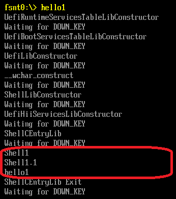
直接运行,输出如下:
用exec4加载之后输出如下:
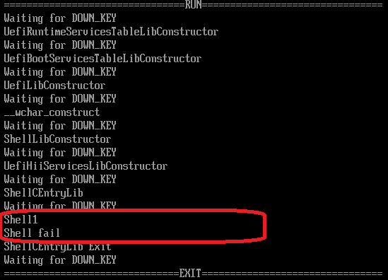
可以看到,两种方式下,运行路径是不同的。
最后的结论:产生问题的原因是,当我们用 StartImage 运行一个 CLib程序的时候,Clib带入的函数找不到 Efi Shell Interface (要用这个Interface 的原因是希望取命令行参数传给被调用者)。找不到的时候就报错,报告一个加载不成功。
本文提到的 hello1 hello2 exec4 的源代码下载:
exec4
Hello2
Hello1
参考:
1.http://www.lab-z.com/utpk/ UEFI Tips 用按键做Pause
2.http://www.lab-z.com/22applicationentry/ Application的入口分析
我一直在使用 VirtualBox 虚拟机,忽然想起可以通过设置串口的方式来进行Windbg对虚拟机中的OS进行调试,这就意味着同样也可以使用串口来进行虚拟机和主机的通讯。
具体的操作是根据【参考1】进行的。
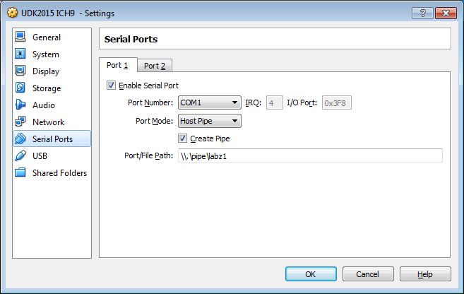
在虚拟机中调整Settings->Serial Ports的设置,可以看到VirtualBox支持2个串口。在Enable串口之前,进入虚拟机只有一个 LPT1 (我不知道是怎么来的) 。
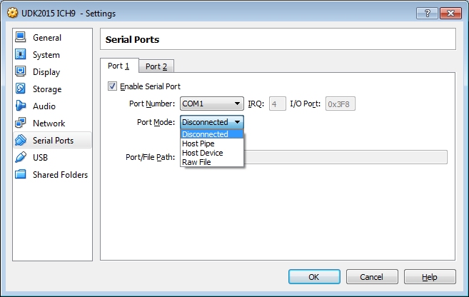
Disconnected 未连接,虚拟机中会出现串口,但是不和任何实际设备对应
Host Pipe 主机管道,选择之后会要求你输入一个管道的名称。虚拟机中对于串口的访问都会发生在这个管道上。管道名称是 \\.\pipe\
Host Device主机设备,可以选择主机上的一个设备比如 com1。虚拟机上对于串口的访问重新发送/接收到这个设备上。
Raw File 裸文件,可以设置主机的一个文件。看起来这个功能更多只是用来看一下串口的Log,应该不能用作交互控制。
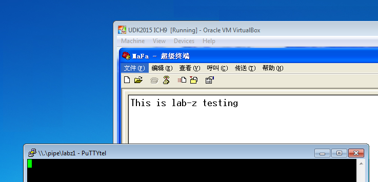
例子:我设置一个名称为 labz1 的pipe。
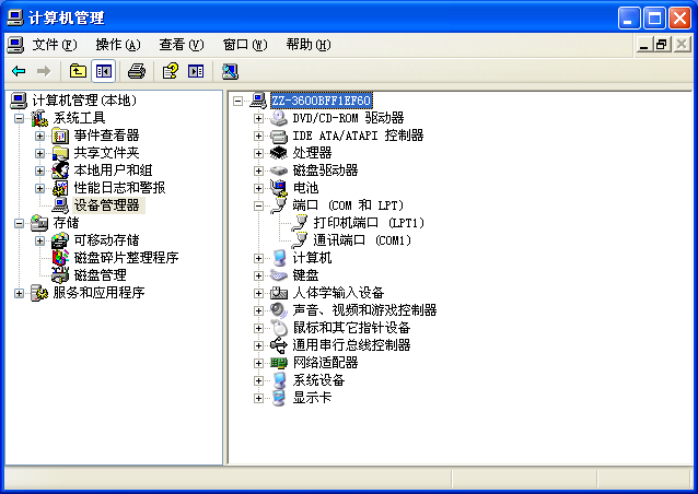
正常启动进入虚拟机(XP系统)
可以看到,有一个com1
打开超级终端,使用com1通讯
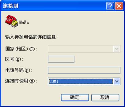
此外其他配置使用默认即可
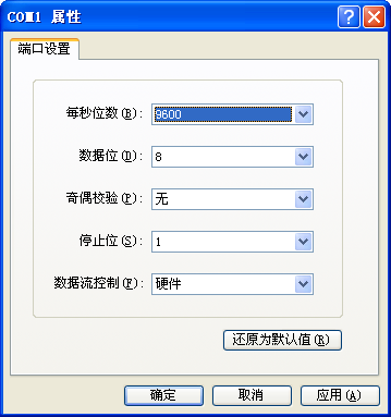
设置 Putty(这个软件运行在虚拟机之外) 如下
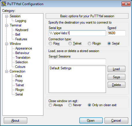
这时,在Putty中输入字符可以在虚拟机中受到,反之亦可。
参考:
1. http://www.crifan.com/summary_how_to_configure_virtualbox_serial_port/ 【详解】如何配置VirtualBox中的虚拟机的串口
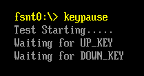
很多年前,我去AMI学习,偶然间看到他们在代码中加入通过 60/61 Port来读取键盘按键信息实现一个按需Delay ,深以为意。今天偶然间想起来,在调试Application 的时候,配合屏幕输出也可以用这样的方式来进行Debug。
下面是一个例子:
#include  <Uefi.h>
#include  <Library/UefiLib.h>
#include  <Library/ShellCEntryLib.h>


extern EFI_BOOT_SERVICES         *gBS;
extern EFI_SYSTEM_TABLE		 *gST;
extern EFI_RUNTIME_SERVICES 	 *gRT;

#define SCAN_NULL       0x0000
#define SCAN_UP         0x0001
#define SCAN_DOWN       0x0002
#define SCAN_ESC        0x0017

int
EFIAPI
main (
  IN int Argc,
  IN CHAR16 **Argv
  )
{
  EFI_INPUT_KEY	Key;
  EFI_STATUS		Status;
  gST->ConOut->OutputString(gST->ConOut,L"Test Starting.....\n\r");
  gST->ConOut->OutputString(gST->ConOut,L"Waiting for UP_KEY\n\r");

  Key.ScanCode=SCAN_NULL;
  while (SCAN_UP!=Key.ScanCode)
    {
		Status= gST -> ConIn -> ReadKeyStroke(gST->ConIn,&Key);
	}

  gST->ConOut->OutputString(gST->ConOut,L"Waiting for DOWN_KEY\n\r");
  Key.ScanCode=SCAN_NULL;
  while (SCAN_DOWN!=Key.ScanCode)
    {
		Status= gST -> ConIn -> ReadKeyStroke(gST->ConIn,&Key);
	}
  return EFI_SUCCESS;
}
通过按光标向上和向下继续运行,运行结果:
完整文件下载
国内玩 Processing 的就很少,玩 OpenCv的更少,有人问到了这里我抽空研究了一下。
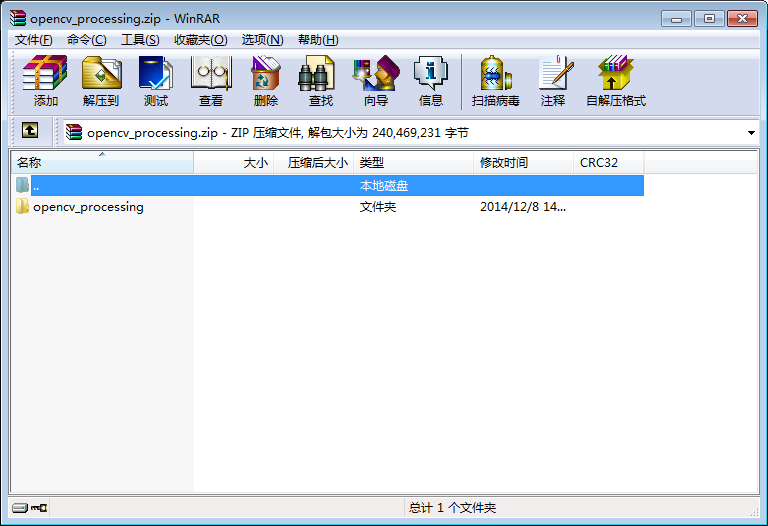
首先,要下载OpenCv for Processing,官方网站是https://github.com/atduskgreg/opencv-processing。我是在这个页面下载的https://github.com/atduskgreg/opencv-processing/releases 0.5.2 的版本。
下载之后直接打开是这样的:
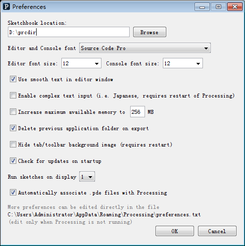
然后,还是和之前文章【参考1】提到的安装方式相同,检查 Preferences 设定,特别提醒,目录不可以有空格或者中文。
之后,打开d:\prcdir\libraries 目录,把前面的全部内容都丢进去
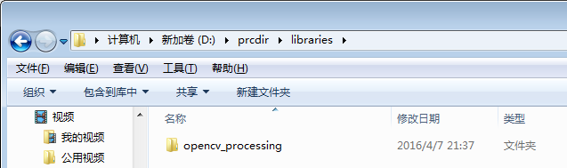
再次打开 processing ,library目录下出现 OpenCv 即正确。
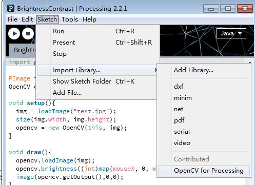
可以直接运行这个库自带的各种例子。
我上传了本文提到的库到 baidu云上,有需要的朋友可以下载,如果有问题也可以直接给我发eMail。
链接:http://pan.baidu.com/s/1jHSPV74 密码:hanc
参考:
1. http://www.lab-z.com/promodel/ Processing导入模型