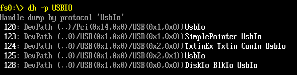
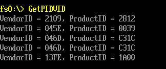
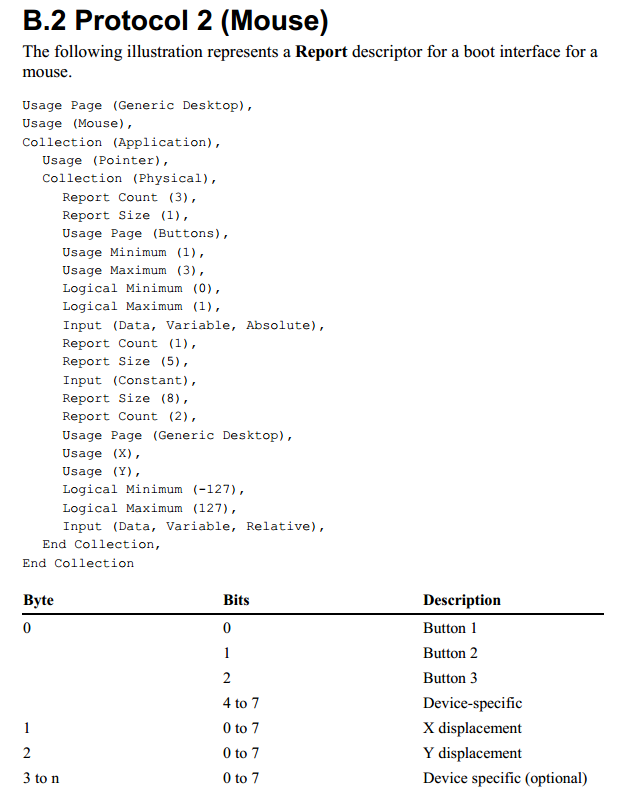
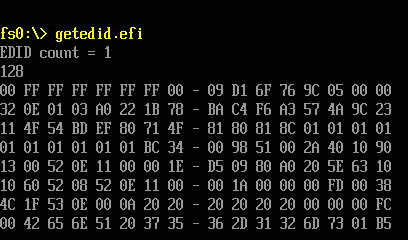
前面《获得 USB 设备的PID和VID》中提到 USB 鼠标上面有一个 SimplePointer 的 Protocol。 本文介绍一下这个 Protocol 的使用。
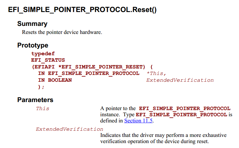
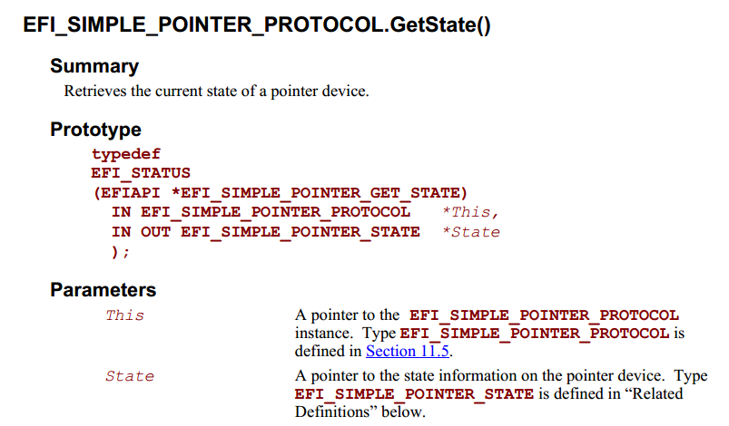
在【参考1】上提到EFI_SIMPLE_POINTER_PROTOCOL 的作用是获得鼠标或者轨迹球的输入数据。
“This would include devices such as mice and trackballs.
The EFI_SIMPLE_POINTER_PROTOCOLallows information about a pointer device to be
retrieved. This would include the status of buttons and the motion of the pointer device since the last
time it was accessed. This protocol is attached the device handle of a pointer device, and can be used
for input from the user inthe preboot environment.”
程序原理:首先用 LocateProtocol 取得EFI_SIMPLE_POINTER_PROTOCOL (这里假设系统中只有一个),然后做一次 Reset ,通过这个动作也确定设备是否可以使用。
之后,不断使用 GetState 轮询,如果发现前后两次获得的信息不同那么就输出解析结果,打印当前鼠标的状态。
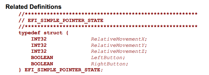
特别注意,取得的信息如下,是一个 INT32 类型的 RelativeMovement 数值,这个数值必须通过 EFI_SIMPLE_POINTER_MODE 中给出来的 UINT64类型的Resolution 除一次才能得到真正的移动信息。
最终的程序如下:
#include  <Uefi.h>
#include  <Library/UefiLib.h>
#include  <Library/ShellCEntryLib.h>
#include  <Protocol/SimplePointer.h>

extern EFI_BOOT_SERVICES         *gBS;
extern EFI_SYSTEM_TABLE		 *gST;
extern EFI_RUNTIME_SERVICES 	 *gRT;

// Include/Protocol/SimplePointer.h
EFI_GUID gEfiSimplePointerProtocolGuid  = { 0x31878C87, 0x0B75, 0x11D5,
			{ 0x9A, 0x4F, 0x00, 0x90, 0x27, 0x3F, 0xC1, 0x4D }};

int
EFIAPI
main (
  IN int Argc,
  IN CHAR16 **Argv
  )
{
	EFI_STATUS	Status;
	EFI_SIMPLE_POINTER_PROTOCOL	*Mouse;
	EFI_SIMPLE_POINTER_STATE	Last,Current;
	EFI_INPUT_KEY				Key;
	INT32		X,Y,Z;

	//Get MP_Service Protocol
	Status = gBS->LocateProtocol (&gEfiSimplePointerProtocolGuid, NULL, (VOID**)&Mouse);
	if (EFI_ERROR (Status)) {
		Print(L"Unable to initialize EFI_SIMPLE_POINTER_PROTOCOL protocol interface!");
		return EFI_UNSUPPORTED;
	}

	Status = Mouse->Reset(Mouse,TRUE);
	if (EFI_ERROR (Status)) {
		Print(L"The device is not functioning correctly and could not be reset!");
		return EFI_UNSUPPORTED;
	}

	gST-> ConOut -> ClearScreen(gST->ConOut);
    Print(L"Resolution: [%lX] [%lX] [%lX] \n",
			Mouse->Mode->ResolutionX,
			Mouse->Mode->ResolutionY,
			Mouse->Mode->ResolutionZ);


	while (1) {
		Status = Mouse->GetState(Mouse,&Current);
		if (memcmp(&Current,&Last,sizeof(EFI_SIMPLE_POINTER_STATE))!=0) {

			X=(INT32) ( Current.RelativeMovementX / Mouse->Mode->ResolutionX);
			Y=(INT32) (Current.RelativeMovementY / Mouse->Mode->ResolutionY);
			Z=(INT32) ( Current.RelativeMovementZ / Mouse->Mode->ResolutionZ);

			Print(L"X=[%d] Y=[%d] Z=[%d] ",
					X,
					Y,
					Z);
			Current.LeftButton?
					Print(L"[Left Click]"):
					Print(L"[No Left   ]");
			Current.RightButton?
					Print(L"[Right Click]\n"):
					Print(L"[No Right   ]\n");
			memcpy(&Last,&Current,sizeof(EFI_SIMPLE_POINTER_STATE))	;
		}
		Status = gST -> ConIn -> ReadKeyStroke (gST->ConIn,&Key);
		if (Status== EFI_SUCCESS) {
			break;
		}
	}
	return EFI_SUCCESS;
}
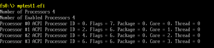
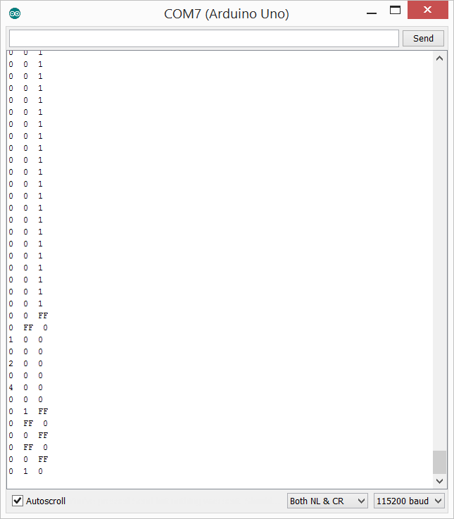
运行结果:
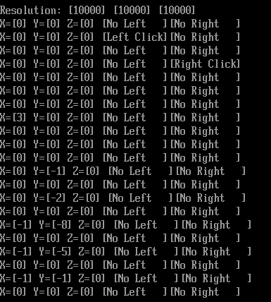
上面可以看到有一些前后没有变化的数据也被打印出来,这个可能是因为取得的原始数据有不同,但是做过除法之后数据是相同的导致的。
关于上面程序需要注意的地方:
1.EDK自带的模拟环境虽然能找到这个 Protocol 但是实际上不会有数据出来的。我试验了很久才发现,同样的程序实体机中跑的很好,但是模拟器不会有结果,所以不能在模拟环境中实验;
2.在处理INT32 INT64输出时要特别注意输出方式,否则会有奇怪的结果。
完整的代码下载:
micetest1
参考:
1. UEFI Spec 2.4 P461