Arduino Leonarado 和其他型号相比,最大的特点是可以方便的将自身模拟为USB键盘和鼠标。从USB总线的角度来说,数据通讯本身是双向的。从整体角度来说键盘只是输入设备,并没有输出的能力,但是如果仔细观察会发现键盘上有三个指示灯,分别是:NumLock,ScrollLock和CapsLock。这三个指示灯作用如下:
1. Num Lock 是副键盘中数字键盘的开关。在这个键对应的键盘指示灯关闭的情况下,小键盘的按键用来移动光标(上下左右、行首、行尾等等),在这个键对应的键盘指示打开的情况下,即锁定数字键,小键盘的按键用来输入数字;
2. Caps Lock 是大小写锁定键,在这个键对应的键盘指示灯关闭的情况下,键盘输入的字母都是小写,否则键盘输入都为大写;
3. Scroll lock (滚动锁定键)最初是用来设计为DOS下自动滚动屏幕的,但是进入Windows出现图形化的界面之后,这个按键就没有用途了,只是为了兼容等等考虑在通用键盘设计上仍然有所保留。
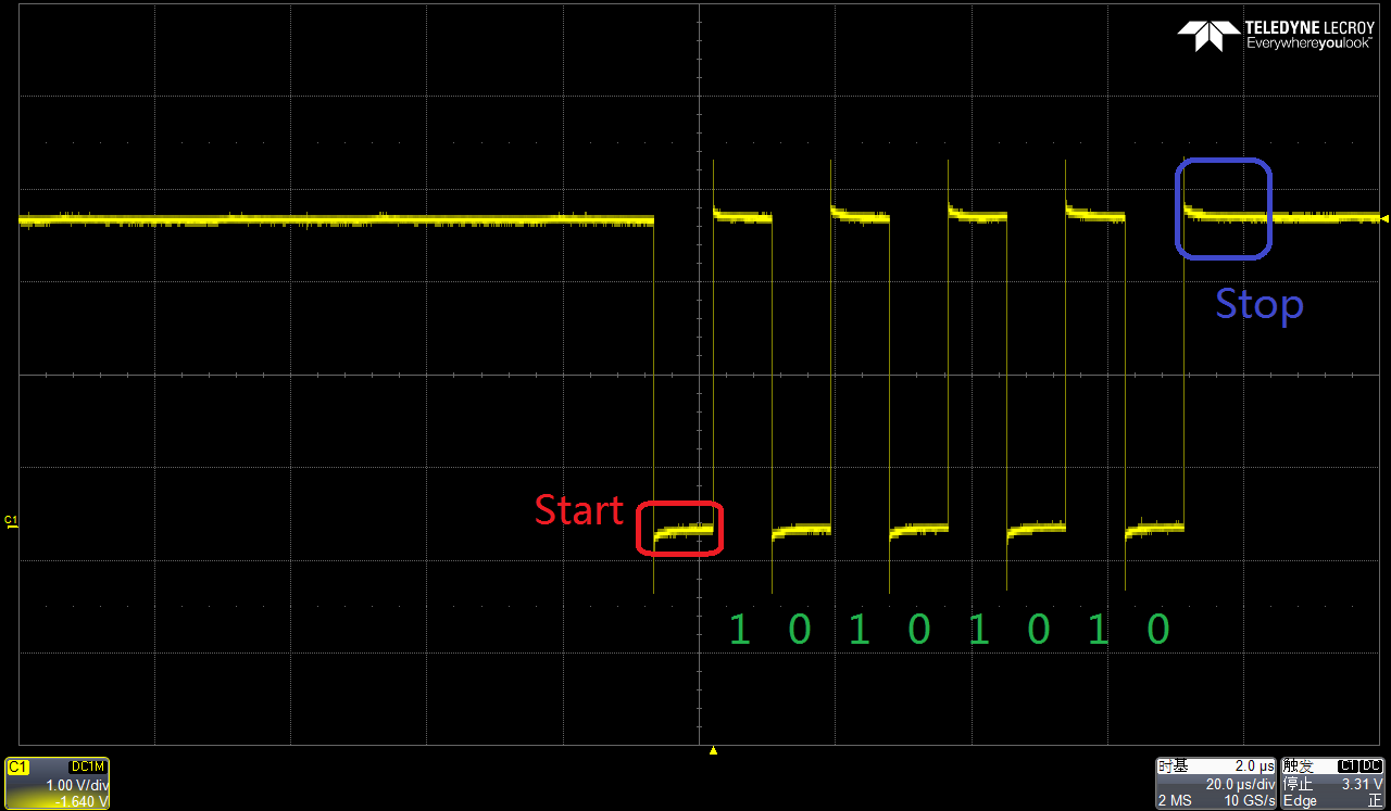
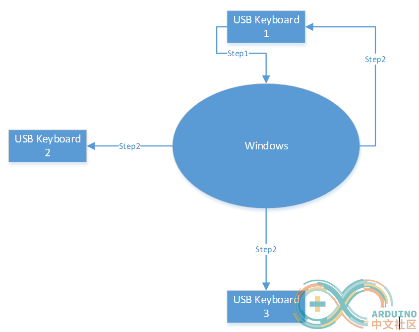
如果你的电脑有两个以上的键盘,还能观察到一个有趣的现象:在一个键盘上按下上述三个键中的某一个,那么其他的键盘状态也会跟着发生变化。原理上来说,是Windows会将收到的切换信息再“广播”出去,保证所有的键盘状态都是同步的。我用USB逻辑分析仪抓包,当在其他键盘上按下NumLock时,系统会向每一个USB键盘发出广播。比如:下面系统中有3个键盘,当键盘1按下 NumLock 后,系统还会通知全部三个键盘“NumLock状态改变”的消息。
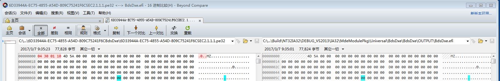
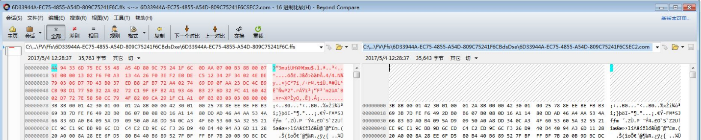
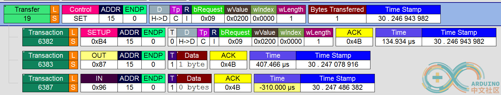
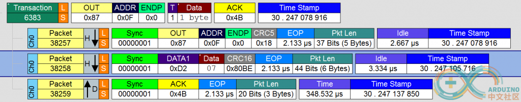
我们无需关心Windows中消息的格式,对于USB来说,USBHost (Windows的PC),会送出一个 SET Package来通知 USB Device(USB 键盘)。下图是我用USB逻辑分析仪抓包的结果:

进一步展看查看协议,是发送了 07 给USB 键盘
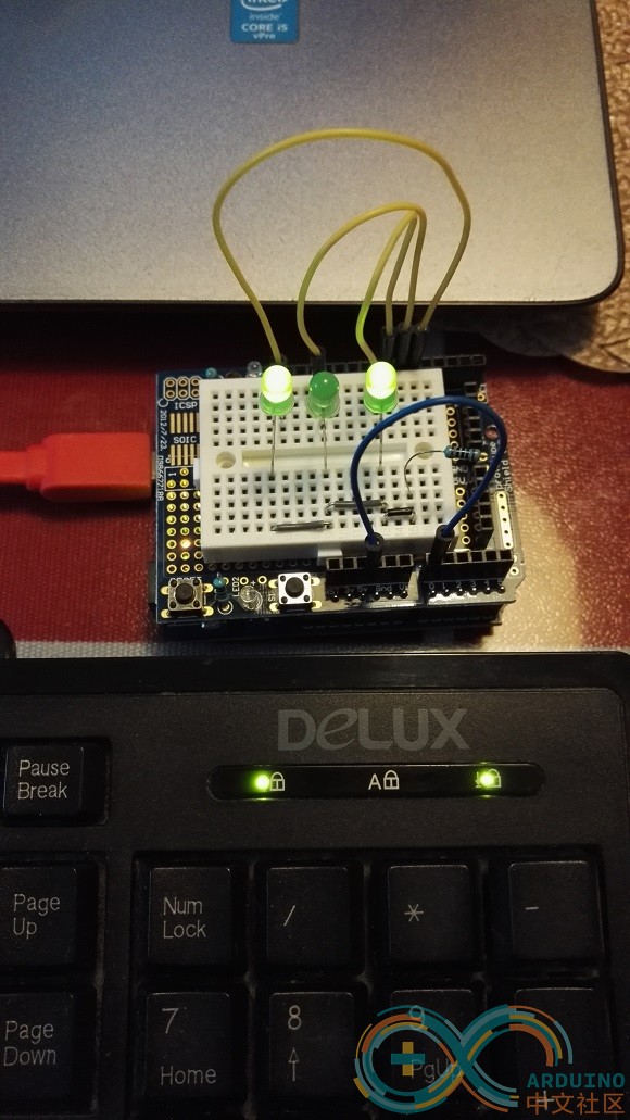
上面的原理可以帮助我们在Arduino Leonarado上实现。简单起见,我们的目标是在ArduinoLeonarado 上装上三个LED,让这三个LED和我的 USB键盘上三个LED实现同步。原生的ArduinoIDE 并没有设计这个功能,因此,需要对源代码进行修改:
第一个需要修改的地方是 \arduino\libraries\Keyboard\src\Keyboard.cpp 中的 USBKeyboard的HID 描述符(Descriptor)。增加了下面斜体字表示的部分:
0x95, 0x08, // REPORT_COUNT (8)
0x81, 0x02, // INPUT (Data,Var,Abs)
0x95, 0x01, // REPORT_COUNT (1)
0x75, 0x08, // REPORT_SIZE (8)
0x81, 0x03, // INPUT (Cnst,Var,Abs)
//ZT_DEBUG
[i] 0x95, 0x05, // REPORT_COUNT (5)
0x75, 0x01, // REPORT_SIZE (1)
0x05, 0x08, // USAGE_PAGE (LEDs)
0x19, 0x01, // USAGE_MINIMUM (1)
0x29, 0x05, // USAGE_MAXIMUM (5)
0x91, 0x02, // OUTPUT (Data,Var,Abs) // LED report
0x95, 0x01, // REPORT_COUNT (1)
0x75, 0x03, // REPORT_SIZE (3)
0x91, 0x01, // OUTPUT (Constant) // padding[/i]
//ZT_DEBUG
0x95, 0x06, // REPORT_COUNT (6)
0x75, 0x08, // REPORT_SIZE (8)
0x15, 0x00, // LOGICAL_MINIMUM (0)
0x25, 0x65, // LOGICAL_MAXIMUM (101)
0x05, 0x07, // USAGE_PAGE (Keyboard)
当然,具体作用请参考USB HID协议对照解读。简单的解释:修改之前的描述符只有INPUT部分,就是键盘告诉系统“我只能发出数据”;增加部分的作用是键盘告诉系统能够接收HOST过来的状态信息(USB协议中,INPUT指的是设备对主机的方向,OUTPUT指的是主机对设备)。我们的修改是加入“我还能接收”的能力。如果不声明这样的能力,系统不会将数据发送过来,具体实验中,一些USB接口的小键盘上面的LED不会跟随主机状态变化。
下面需要做的就是实际处理数据了。1.6.X 系列的代码和之前的差别很大,对于键盘这部分是分开在 HID 和Keyboard 的类中。
Keyboard 只有输出的代码,通过调用 HID 类来进行发送的处理。因此,我们需要在HID 类中开一个接口。
重新定义如下:
处理部分, 在\arduino\hardware\arduino\avr\libraries\HID\src\HID.cpp 中的 boolHID_::setup(USBSetup& setup)函数中,当我们收到 Set_Report 就是系统发过来的关于LED的设置,我们取下来即可。
对于 HID 开一个接口,直接返回即可
uint8_t HID_::getLedStatus(void)
{
returnled;
}
我们给用户的接口是 Keyboard 类,我们要在上面田间一个读取的接口,
在这只文件中声明 \arduino\libraries\Keyboard\src\Keyboard.h
在s\arduino\libraries\Keyboard\src\Keyboard.cpp 文件中实现
编写一个例子,使用 Arduino 同步显示当前键盘的LED状态:
D5 最左侧灯,D6中间灯,D7 最右侧灯。
#include <Keyboard.h>

uint8_t old=0xFF,n=0xFF;

void setup() {
  pinMode(A0, INPUT_PULLUP);
  pinMode(5,OUTPUT);
  pinMode(6,OUTPUT);
  pinMode(7,OUTPUT);

  Keyboard.begin();

  Serial.begin(9600);
  while (digitalRead(A0) == HIGH) {
    // do nothing until pin 2 goes low
    delay(500);
  }
}

void loop() {

  n=Keyboard.getLedStatus();
  if (n!=old) {
     Serial.println(n);
     old=n;
     if (0!=(n&1) +) {
          digitalWrite(5,HIGH);
      }
     else {
          digitalWrite(5,LOW);
      }
     if (0!=(n&2)) {
          digitalWrite(6,HIGH);
      }
     else {
          digitalWrite(6,LOW);
      }
     if (0!=(n&4)) {
          digitalWrite(7,HIGH);
      }
     else {
          digitalWrite(7,LOW);
      }
  }
  delay(100);
}

工作的视频