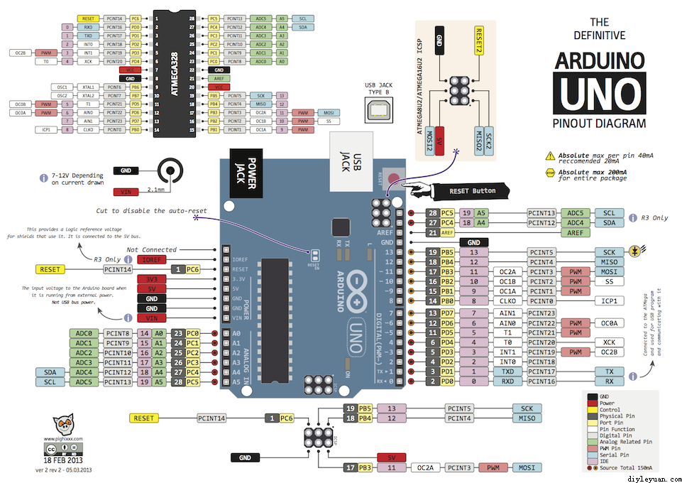
实验设备是一块 Arduino Uno 16M (是那种没有品牌的兼容版),示波器是 Teledyne Lecory Wave Runner 606Zi 600Mhz 20GS/s。
第一个实验:只使用DigitalWrite 能制造出来的最大频率是多少?
首先试试最通用的 digitalWrite 的方法不断在高低之间反转
const int PinA =  13;

void setup() {
  pinMode(PinA, OUTPUT);
  digitalWrite(PinA,LOW);
}

void loop() {
  digitalWrite(PinA,HIGH);
  digitalWrite(PinA,LOW);
  digitalWrite(PinA,HIGH);
  digitalWrite(PinA,LOW);
  digitalWrite(PinA,HIGH);
  digitalWrite(PinA,LOW);
  delay(500);
}
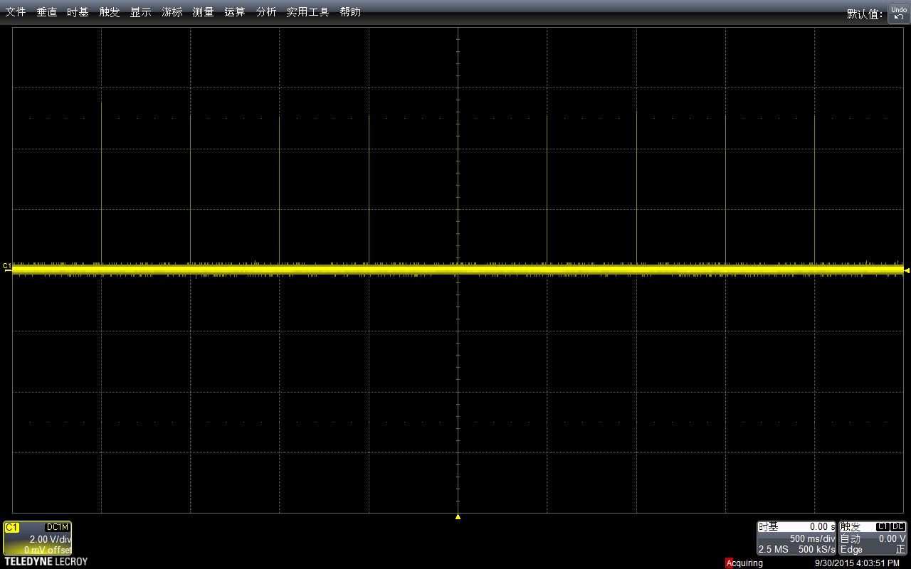
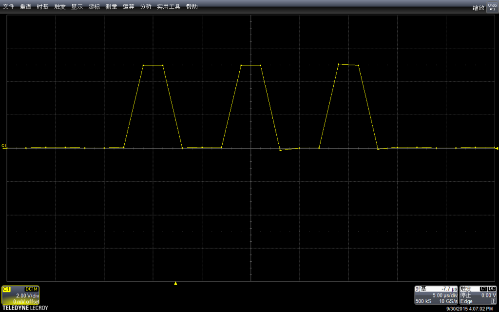
使用示波器抓图如下(下面的所有介绍都是具体解说在上,抓取波形在下):
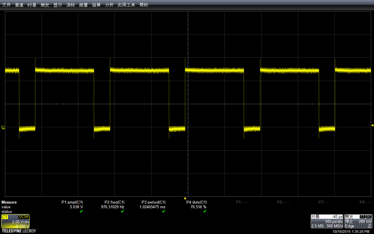
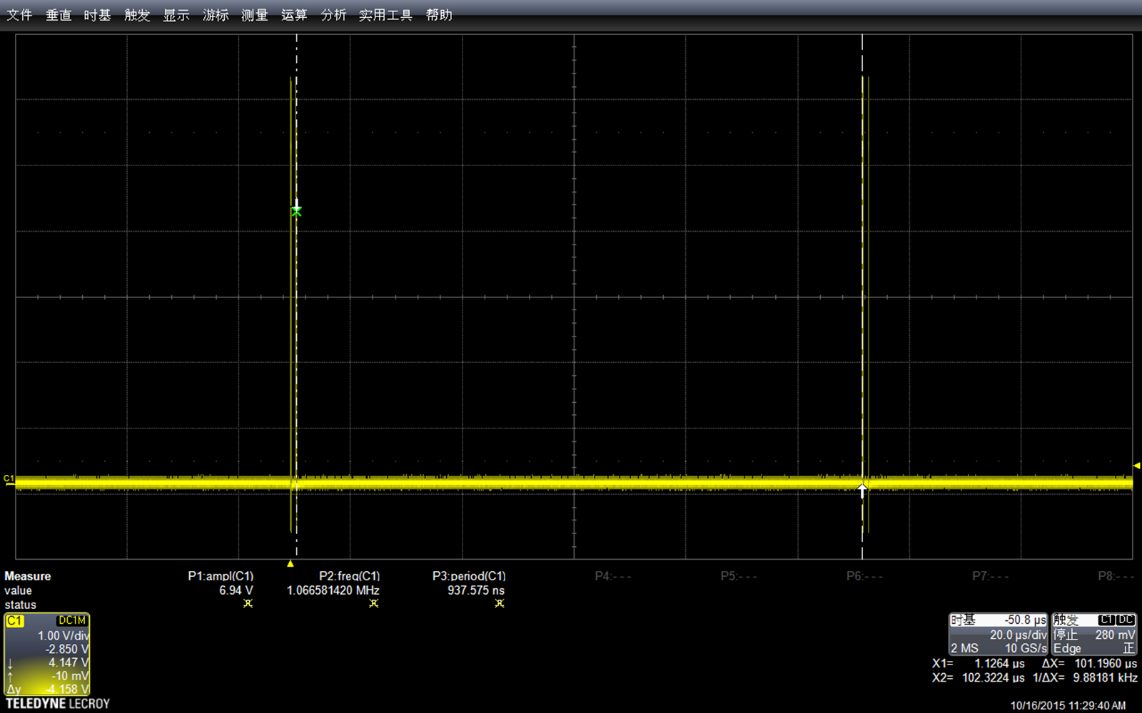
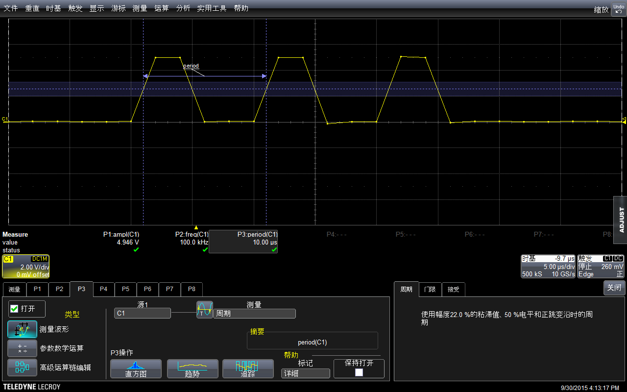
我们设置的Delay 是500ms, 然后示波器的水平方向每一格也是500ms,垂直方向是电压,当前选择每格2V,因此看起来差不多是5v左右,符合预期。

我选择了了Stop功能,放大波形进行查看。可以看到,最上面波形中黄色竖线实际上是一组波形,就是对应我们的拉高拉低。
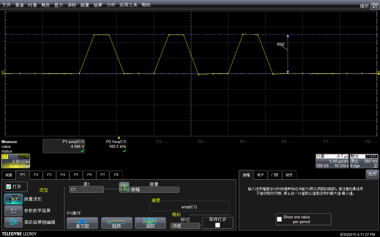
示波器有测量功能,直接调用该功能进行测试:可以看到幅度是4.946V,示波器还标记出来具体的测试方法,这在测量一些不是那么“规整”的波形时非常有用。

再用示波器自动测量一下频率:是100kHz。
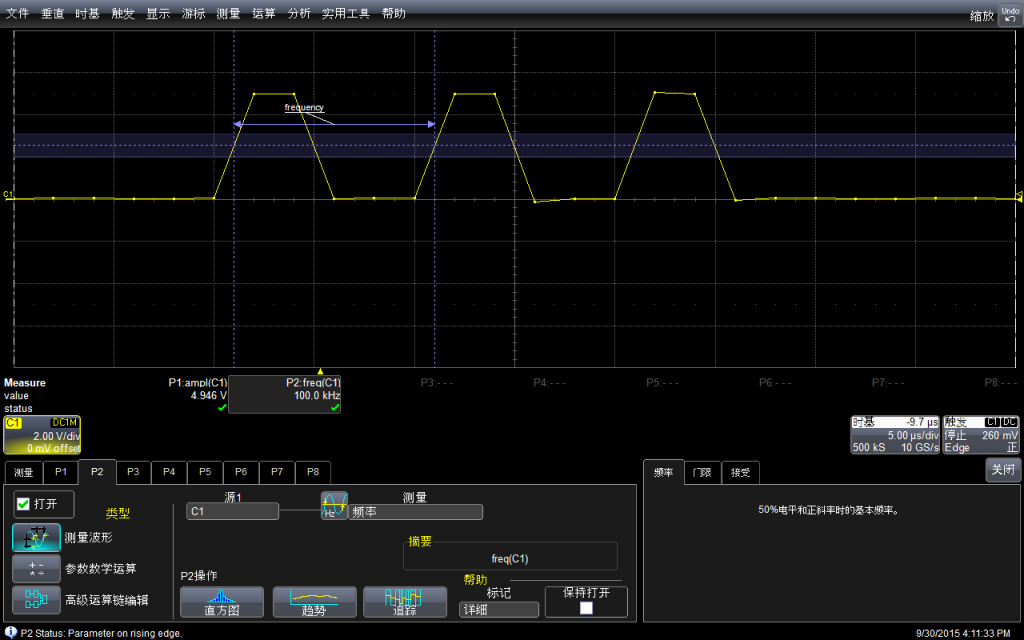
可以在菜单中选择测试的具体方法(比如,测试频率通用的方法是波形上升沿50%的位置)
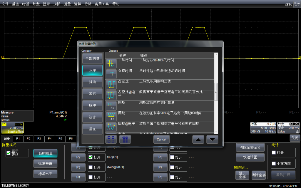
再测量周期(其实给出来了频率,周期是可以直接换算出来的)
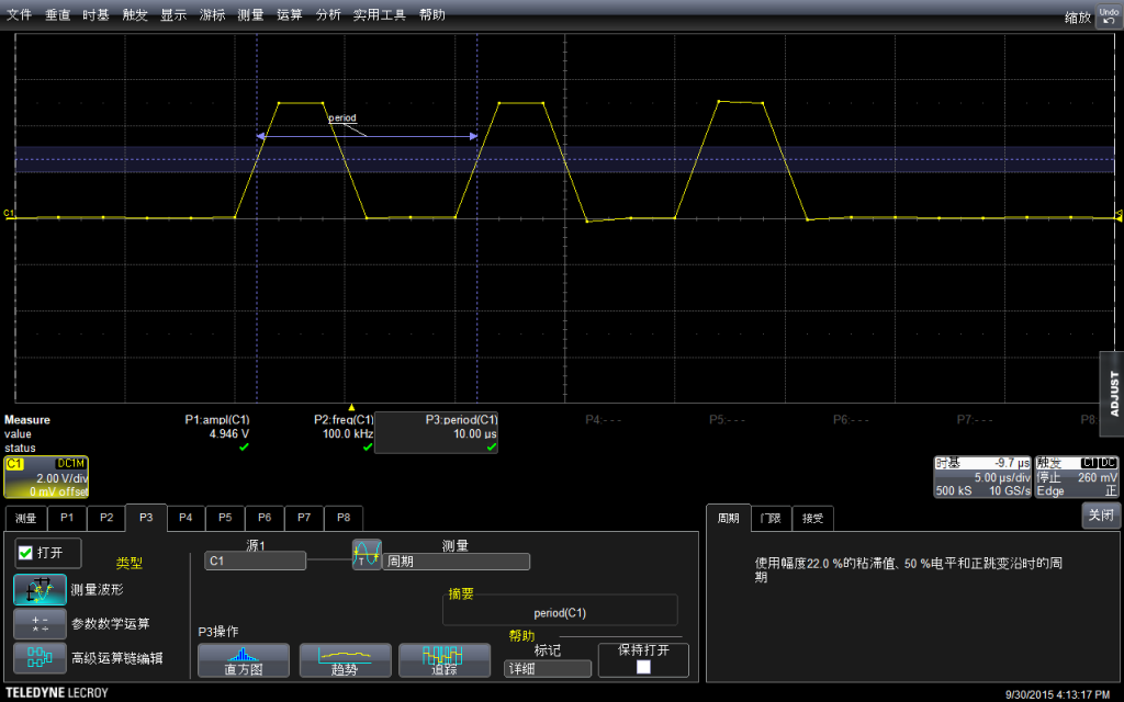
结论:如果我们用 DigitalWrite拼命上下拉,最高是可以输出100Khz频率的。
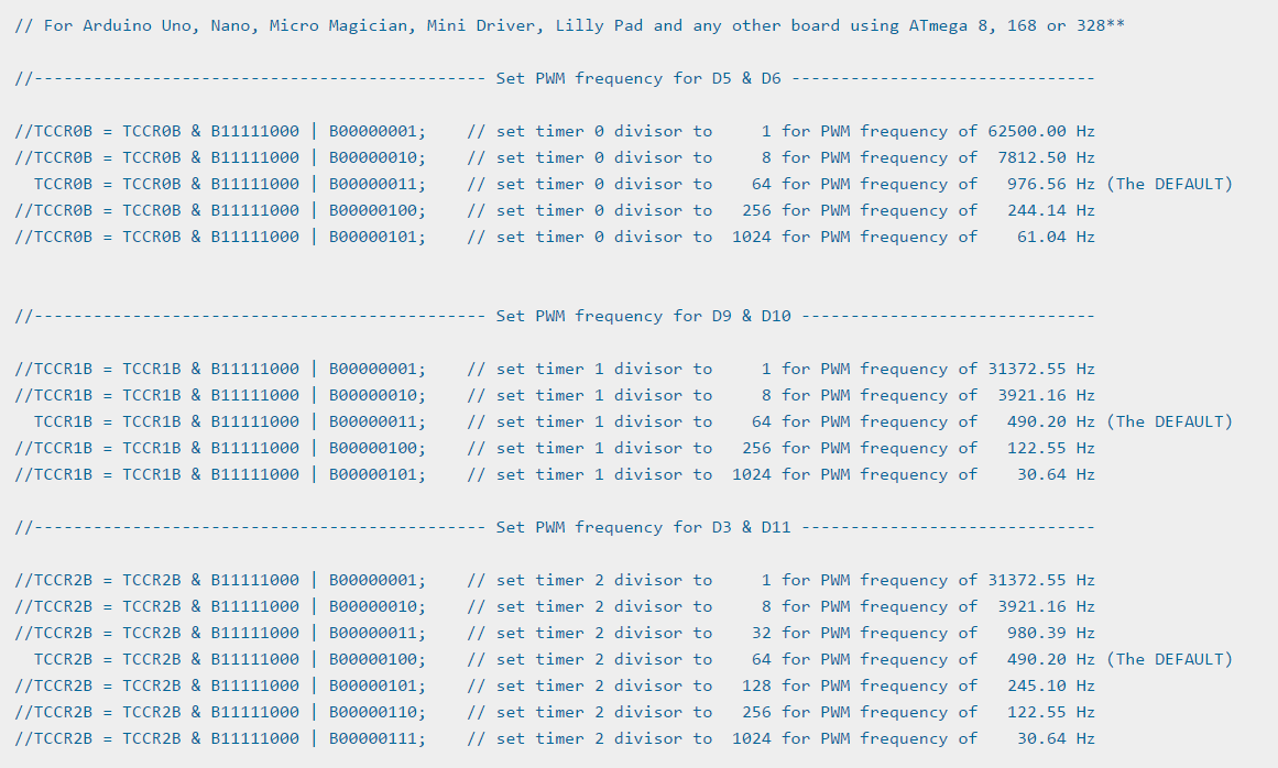
之后,我们再试试使用PortB赋值直接拉出来的频率是多少?关于 PortB 指令可以在【参考1】看到。
const int PinA =  13;
void setup() {
  pinMode(PinA, OUTPUT);
  digitalWrite(PinA,LOW);
}

void loop() {
  PORTB = B100000; //digitalWrite(PinA,HIGH);
  PORTB = B000000; //digitalWrite(PinA,LOW);
  PORTB = B100000; //digitalWrite(PinA,HIGH);
  PORTB = B000000; //digitalWrite(PinA,LOW);
  PORTB = B100000; //digitalWrite(PinA,HIGH);
  PORTB = B000000;  //digitalWrite(PinA,LOW);

  delay(500);
}
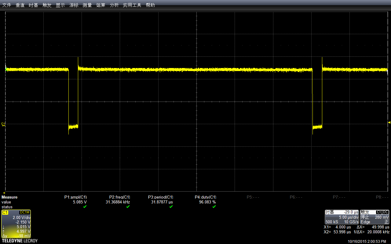
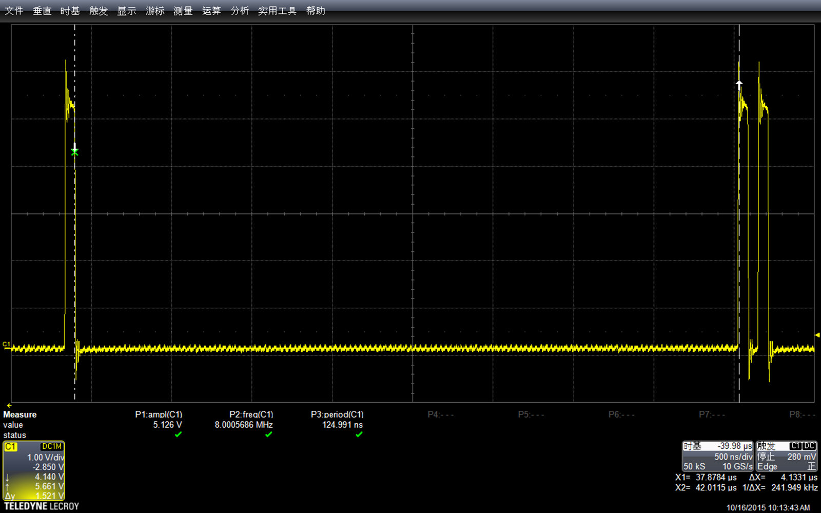
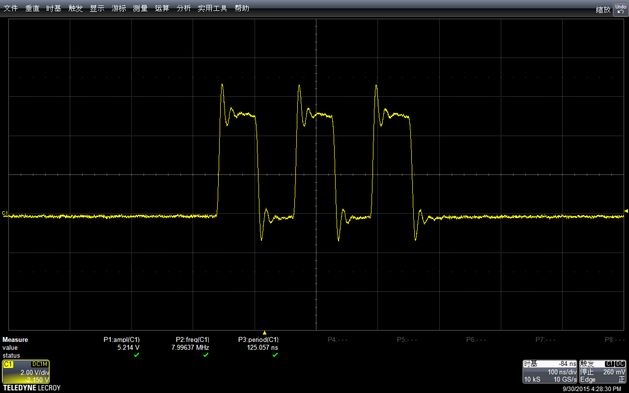
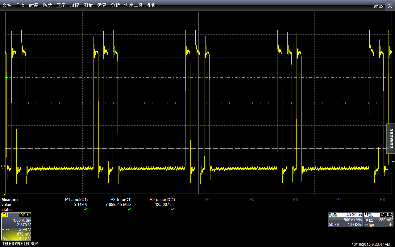
看起来下面波形感觉畸变比较严重(这里:解释一下,前面图看起来平滑的原因是采样时间导致的。比如,我的示波器单位时间可以采样500个点,如果我采样1s,放大之后,在1ms范围内只有5个点。如果我直接采样1ms,那么会有500个点来描绘波形,看起来自然“平滑”得多)

测试幅度,会达到5.248v

同样,使用自带功能测试频率:惊人的 7.99590Mhz
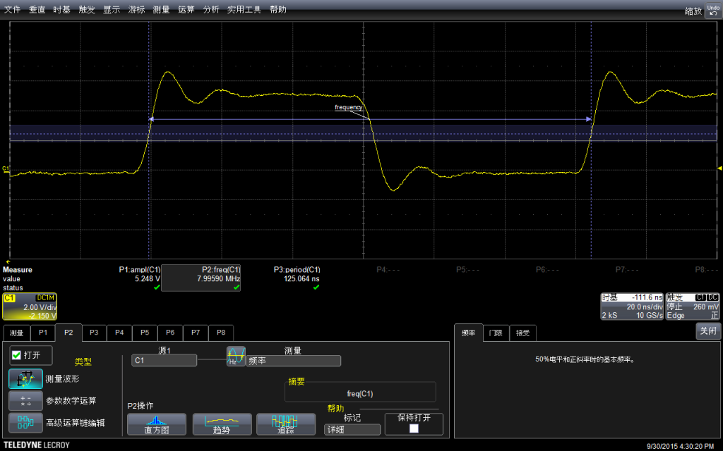
因为一个周期里面实际上是有两条指令的(拉上拉下),已经非常接近主芯片的16Mhz了。
根据上面的结果引申的问题:如何同时拉高两个Port?
首先我们尝试一下 DigitalWrite的方法
const int PinA =  13;
const int PinB =  8;
void setup() {
  pinMode(PinA, OUTPUT);
  digitalWrite(PinA,LOW);

  pinMode(PinB, OUTPUT);
  digitalWrite(PinB,LOW);
}

void loop() {
  digitalWrite(PinA,HIGH);
  digitalWrite(PinB,HIGH);
  digitalWrite(PinA,LOW);
  digitalWrite(PinB,LOW);

  delay(500);
}
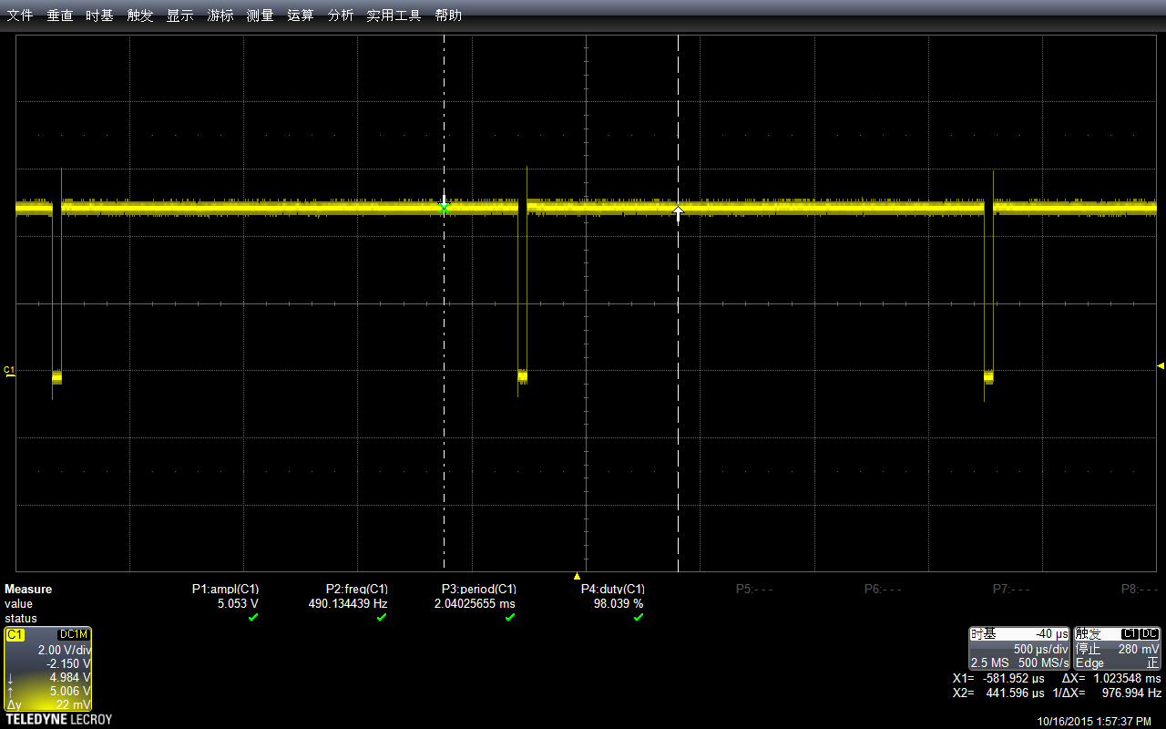
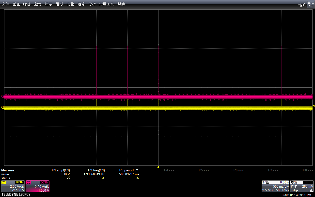
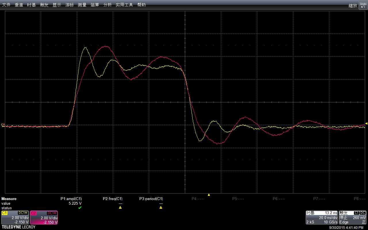
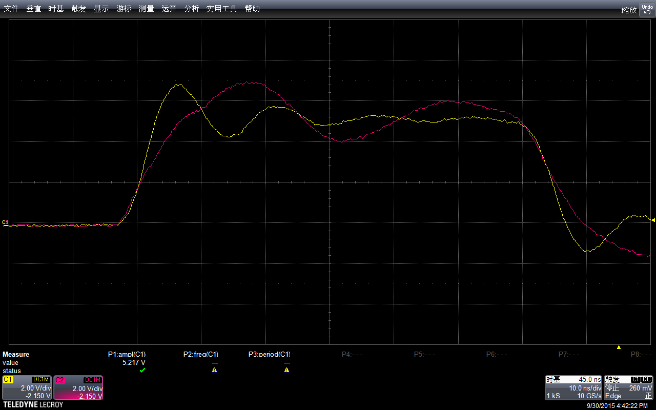
下图可以看到,注意我设置两个信号起始电压不同,为了观测方便,所以会一个上一个下

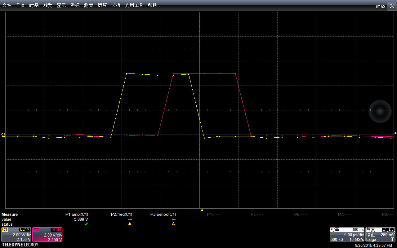
放大之后查看
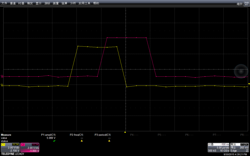
为了方便观看,我设置他们电压起点相同,可以看出他们差不多有1个水平格子的差别(5us)。对于这个差异可以在【参考2】初步了解一下。
再尝试PortB 直接赋值的方法
const int PinA =  13;
const int PinB =  8;
void setup() {
  pinMode(PinA, OUTPUT);
  digitalWrite(PinA,LOW);

  pinMode(PinB, OUTPUT);
  digitalWrite(PinB,LOW);
}

void loop() {

  PORTB = B100001; //digitalWrite(PinA,HIGH); digitalWrite(PinB,HIGH);
  PORTB = B000000; //digitalWrite(PinA,LOW); digitalWrite(PinB,LOW);

  delay(500);
}
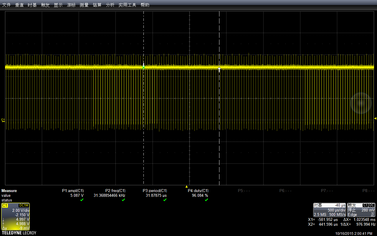
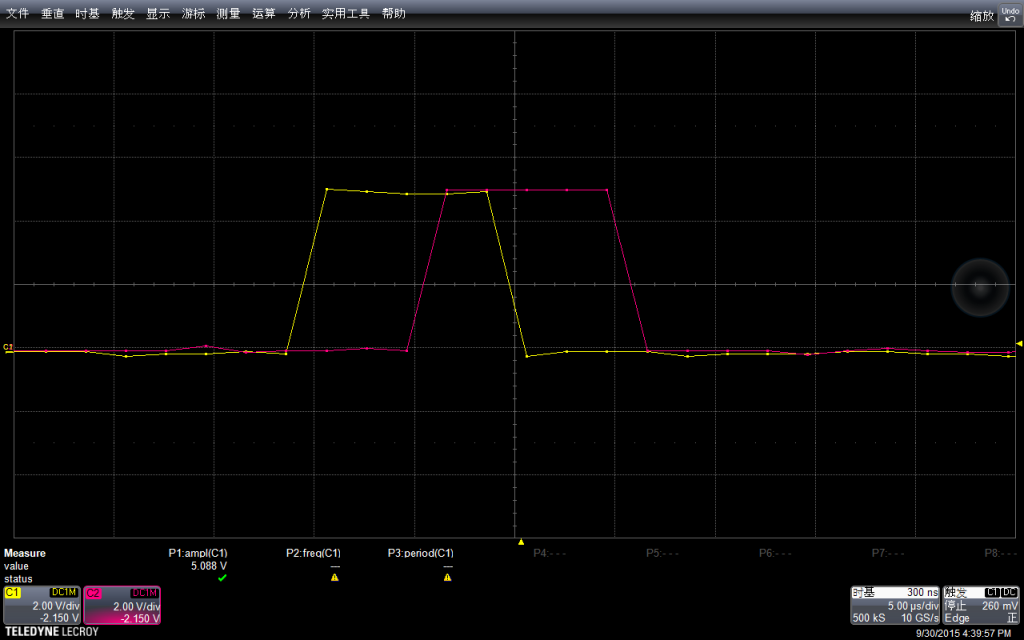
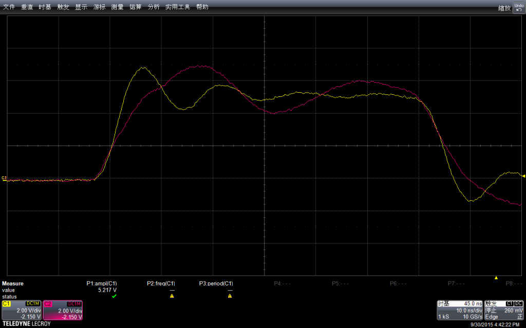
结果上可以看作是同时发出的

再放大查看,纠缠在一起,,波形上的细微差别可能是外围电路导致的。
补记:为了比对,额外实验 DFrobot 的 RomeoBLEV1.0 的板子为了看得清楚,修改程序如下,去掉了 delay
const int PinA =  13;
void setup() {
  pinMode(PinA, OUTPUT);
  digitalWrite(PinA,LOW);
}

void loop() {
  PORTB = B100000; //digitalWrite(PinA,HIGH);
  PORTB = B000000; //digitalWrite(PinA,LOW);
  PORTB = B100000; //digitalWrite(PinA,HIGH);
  PORTB = B000000; //digitalWrite(PinA,LOW);
  PORTB = B100000; //digitalWrite(PinA,HIGH);
  PORTB = B000000;  //digitalWrite(PinA,LOW);
}
先看大范围的,每组3次上升,每组之间的间隔是void loop() { } 中的代码导致的

振幅上和之前的板子差不多 5.13v左右,实际多测试几次也会出现 5.2v。看起来由品牌的板子和无品牌的板子在这方便没有差别。
参考:
1.关于Port x的说明https://www.arduino.cc/en/Reference/PortManipulation
PORTD maps to Arduino digital pins 0 to 7
DDRD – The Port D Data Direction Register – read/write
PORTD – The Port D Data Register – read/write
PIND – The Port D Input Pins Register – read only
PORTB maps to Arduino digital pins 8 to 13 The two high bits (6 & 7) map to the crystal pins and are not usable
DDRB – The Port B Data Direction Register – read/write
PORTB – The Port B Data Register – read/write
PINB – The Port B Input Pins Register – read only
PORTC maps to Arduino analog pins 0 to 5. Pins 6 & 7 are only accessible on the Arduino Mini
DDRC – The Port C Data Direction Register – read/write
PORTC – The Port C Data Register – read/write
PINC – The Port C Input Pins Register – read only
同样,这篇文章中提到了如何同时拉Pin 的方法
Sometimes you might need to set multiple output pins at exactly the same time. Calling digitalWrite(10,HIGH); followed by digitalWrite(11,HIGH); will cause pin 10 to go HIGH several microseconds before pin 11, which may confuse certain time-sensitive external digital circuits you have hooked up. Alternatively, you could set both pins high at exactly the same moment in time using PORTB |= B1100;
2. Arduino 代码机制 http://blog.csdn.net/pinbodexiaozhu/article/details/42641273