Step to UEFI (41) —– x64 的 FreqCalc程序

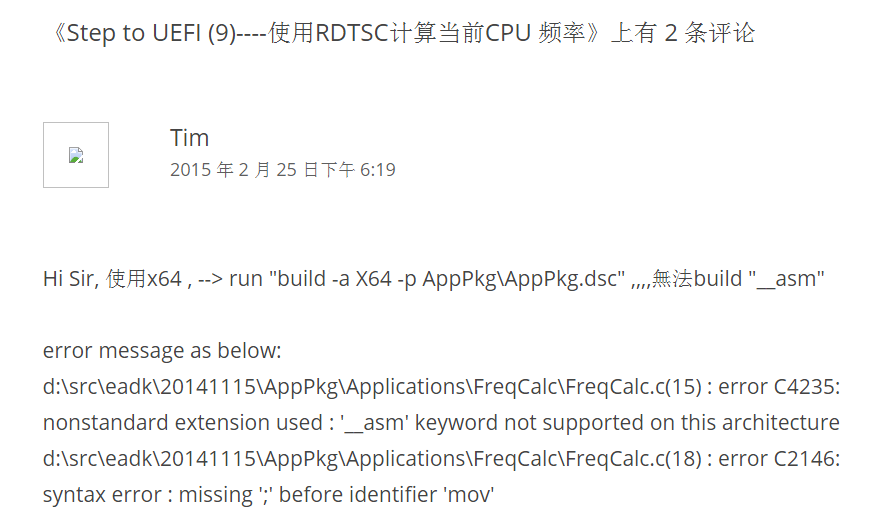
之前的一篇文章《Step to UEFI (9)—-使用RDTSC计算当前CPU 频率》【参考1】给出了一个计算当前CPU频率的方法。不过 Tim 给我留言,他说这篇文章的程序无法在 x64下正常编译:

freq

我猜测原因是因为我的程序使用的内嵌汇编,内嵌汇编无法被X64的编译器正常编译的。关于这个说法可以看【参考2】。

动手在 UDK2014 下面实验,不过在看到描述的问题之前还是要走一段路的。

使用编译命令 build -a X64 -p AppPkg\AppPkg.dsc 得到下面的错误信息

c:\edk\AppPkg\AppPkg.dsc(94): error 000E: File/directory not found in workspace
        c:\edk\PerformancePkg\Library\DxeTscTimerLib\DxeTscTimerLib.inf


检查 AppPkg.dsc

修改

[LibraryClasses.X64]
  TimerLib|PerformancePkg/Library/DxeTscTimerLib/DxeTscTimerLib.inf


修改为

[LibraryClasses.X64]
  TimerLib|PerformancePkg/Library/TscTimerLib/DxeTscTimerLib.inf


再次编译,有下面的错误信息

Processing meta-data .. done!
Building ... c:\edk\MdePkg\Library\BaseLib\BaseLib.inf [X64]
        "C:\Program Files\Microsoft Visual Studio 9.0\Vc\bin\x86_amd64\cl.exe" /Foc:\edk\Build\AppPkg\DEBUG_MYTOOLS\X64\MdePkg\Library\BaseLib\BaseLib\OUTPUT\.\CheckSum.obj /nologo /c /WX /GS- /W4 /Gs32768 /Gy /D UNICODE /O1ib2 /GL /FIAutoG
en.h /EHs-c- /GR- /GF /Zi /Gm /X /Zc:wchar_t /X /Zc:wchar_t /GL- /Ic:\edk\MdePkg\Library\BaseLib\X64  /Ic:\edk\MdePkg\Library\BaseLib  /Ic:\edk\Build\AppPkg\DEBUG_MYTOOLS\X64\MdePkg\Library\BaseLib\BaseLib\DEBUG  /Ic:\edk\MdePkg  /Ic:\edk\M
dePkg\Include  /Ic:\edk\MdePkg\Include\X64 c:\edk\MdePkg\Library\BaseLib\CheckSum.c
'C:\Program' 不是内部或外部命令,也不是可运行的程序或批处理文件。
NMAKE : fatal error U1077: '"C:\Program Files\Microsoft Visual Studio 9.0\Vc\bin\x86_amd64\cl.exe' : return code '0x1' Stop.


build...
 : error 7000: Failed to execute command
        C:\Program Files\Microsoft Visual Studio 9.0\Vc\bin\nmake.exe /nologo tbuild 

build...
 : error 7000: Failed to execute command
        C:\Program Files\Microsoft Visual Studio 9.0\Vc\bin\nmake.exe /nologo tbuild 


build...
 : error F002: Failed to build module
        c:\edk\MdePkg\Library\BaseLib\BaseLib.inf [X64, MYTOOLS, DEBUG]

- Failed -
Build end time: 11:22:09, Mar.09 2015
Build total time: 00:00:03


尝试在命令行窗口直接运行”C:\Program Files\Microsoft Visual Studio 9.0\Vc\bin\x86_amd64\cl.exe” 错误提示是:

C:\EDK>"C:\Program Files\Microsoft Visual Studio 9.0\Vc\bin\x86_amd64\cl.exe"
系统找不到指定的路径。


这是因为目前的编译环境缺少 64位编译器。我使用的是 vs2008 express 版本,默认是没有 64位的cl.exe的。

找到 ‘x86_amd64’ 拷贝到 “C:\Program Files\Microsoft Visual Studio 9.0\VC\bin”

需要的朋友可以在这里下载到 x86_amd64

再次编译,然后就能看到 Tim 说的问题啦

C:\Program Files\Microsoft Visual Studio 9.0\VC\bin

Building ... c:\edk\AppPkg\Applications\FreqCalc\FreqCalc.inf [X64]
        "C:\Program Files\Microsoft Visual Studio 9.0\Vc\bin\x86_amd64\cl.exe" /Foc:\edk\Build\AppPkg\DEBUG_MYTOOLS\X64\AppPkg\Applications\FreqCalc\FreqCalc\OUTPUT\.\FreqCalc.obj /nologo /c /WX /GS- /W4 /Gs32768 /Gy /D UNICODE /O1ib2 /GL /
FIAutoGen.h /EHs-c- /GR- /GF /Zi /Gm /X /Zc:wchar_t /Ic:\edk\AppPkg\Applications\FreqCalc  /Ic:\edk\Build\AppPkg\DEBUG_MYTOOLS\X64\AppPkg\Applications\FreqCalc\FreqCalc\DEBUG  /Ic:\edk\MdePkg  /Ic:\edk\MdePkg\Include  /Ic:\edk\MdePkg\Includ
e\X64  /Ic:\edk\ShellPkg  /Ic:\edk\ShellPkg\Include  /Ic:\edk\MdeModulePkg  /Ic:\edk\MdeModulePkg\Include c:\edk\AppPkg\Applications\FreqCalc\FreqCalc.c
FreqCalc.c
c:\edk\AppPkg\Applications\FreqCalc\FreqCalc.c(15) : error C4235: nonstandard extension used : '__asm' keyword not supported on this architecture
c:\edk\AppPkg\Applications\FreqCalc\FreqCalc.c(18) : error C2146: syntax error : missing ';' before identifier 'mov'
c:\edk\AppPkg\Applications\FreqCalc\FreqCalc.c(18) : warning C4550: expression evaluates to a function which is missing an argument list
c:\edk\AppPkg\Applications\FreqCalc\FreqCalc.c(18) : error C2065: 'mov' : undeclared identifier
c:\edk\AppPkg\Applications\FreqCalc\FreqCalc.c(18) : error C2146: syntax error : missing ';' before identifier 'dword'
c:\edk\AppPkg\Applications\FreqCalc\FreqCalc.c(18) : error C2065: 'dword' : undeclared identifier
c:\edk\AppPkg\Applications\FreqCalc\FreqCalc.c(18) : error C2146: syntax error : missing ';' before identifier 'ptr'
c:\edk\AppPkg\Applications\FreqCalc\FreqCalc.c(18) : error C2065: 'ptr' : undeclared identifier
c:\edk\AppPkg\Applications\FreqCalc\FreqCalc.c(18) : error C2146: syntax error : missing ';' before identifier 'value'
c:\edk\AppPkg\Applications\FreqCalc\FreqCalc.c(19) : error C2065: 'eax' : undeclared identifier
c:\edk\AppPkg\Applications\FreqCalc\FreqCalc.c(19) : error C2146: syntax error : missing ';' before identifier 'mov'
c:\edk\AppPkg\Applications\FreqCalc\FreqCalc.c(19) : error C2065: 'mov' : undeclared identifier
c:\edk\AppPkg\Applications\FreqCalc\FreqCalc.c(19) : error C2146: syntax error : missing ';' before identifier 'dword'
c:\edk\AppPkg\Applications\FreqCalc\FreqCalc.c(19) : error C2065: 'dword' : undeclared identifier
c:\edk\AppPkg\Applications\FreqCalc\FreqCalc.c(19) : error C2146: syntax error : missing ';' before identifier 'ptr'
c:\edk\AppPkg\Applications\FreqCalc\FreqCalc.c(19) : error C2065: 'ptr' : undeclared identifier
c:\edk\AppPkg\Applications\FreqCalc\FreqCalc.c(19) : error C2109: subscript requires array or pointer type
c:\edk\AppPkg\Applications\FreqCalc\FreqCalc.c(20) : error C2065: 'edx' : undeclared identifier
c:\edk\AppPkg\Applications\FreqCalc\FreqCalc.c(20) : error C2143: syntax error : missing ';' before '}'
NMAKE : fatal error U1077: '"C:\Program Files\Microsoft Visual Studio 9.0\Vc\bin\x86_amd64\cl.exe"' : return code '0x2'
Stop.


build...
 : error 7000: Failed to execute command
        C:\Program Files\Microsoft Visual Studio 9.0\Vc\bin\nmake.exe /nologo tbuild 


build...
 : error F002: Failed to build module
        c:\edk\AppPkg\Applications\FreqCalc\FreqCalc.inf [X64, MYTOOLS, DEBUG]

- Failed -
Build end time: 11:26:31, Mar.09 2015
Build total time: 00:01:16


然后就考虑如何解决,网上搜索了一下,有人遇到同样的问题【参考3】,具体的解决方法在【参考4】

简单的说,就是单独写一个 asm 然后在对应的 Inf中声明一下即可。

针对我遇到的问题,程序如下

FreqCalc.inf

## @file
#  Sample UEFI Application Reference EDKII Module
#
#  This is a sample shell application that will print "UEFI Hello World!" to the 
#  UEFI Console based on PCD setting.
#
#  It demos how to use EDKII PCD mechanism to make code more flexible.
#
#  Copyright (c) 2008 - 2011, Intel Corporation. All rights reserved.<BR>
#
#  This program and the accompanying materials
#  are licensed and made available under the terms and conditions of the BSD License
#  which accompanies this distribution. The full text of the license may be found at
#  http://opensource.org/licenses/bsd-license.php
#  THE PROGRAM IS DISTRIBUTED UNDER THE BSD LICENSE ON AN "AS IS" BASIS,
#  WITHOUT WARRANTIES OR REPRESENTATIONS OF ANY KIND, EITHER EXPRESS OR IMPLIED.
#
#
##

[Defines]
  INF_VERSION                    = 0x00010005
  BASE_NAME                      = FreqCalc
  FILE_GUID                      = 6987936E-ED34-44db-AE97-2FA5E4ED2216
  MODULE_TYPE                    = UEFI_APPLICATION
  VERSION_STRING                 = 1.0
  ENTRY_POINT                    = UefiMain 

#
# The following information is for reference only and not required by the build tools.
#
#  VALID_ARCHITECTURES           = IA32 X64 IPF EBC
#

[Sources]
  FreqCalc.c
  ReadTsc1.asm

[Packages]
  MdePkg/MdePkg.dec
  ShellPkg/ShellPkg.dec
  MdeModulePkg/MdeModulePkg.dec

[LibraryClasses]
  UefiApplicationEntryPoint
  UefiLib
  PcdLib
  ShellCEntryLib
  ShellLib


[FeaturePcd]


[Pcd]


然后在FreqCalc.c 写成下面这样,特别注意要声明一下你用的那个汇编语言中的函数名

//
// FreqCalc.C
//

#include <Uefi.h>
#include <Library/UefiLib.h>
#include <Library/ShellLib.h>

EFI_SYSTEM_TABLE	*gST;
EFI_BOOT_SERVICES  	*gBS;

UINT64
EFIAPI
zReadTsc (
  VOID
);

//
// Entry point function - ShowVersion
//
EFI_STATUS
EFIAPI
UefiMain (
  IN EFI_HANDLE        ImageHandle,
  IN EFI_SYSTEM_TABLE  *SystemTable
  )
{

  UINT64  elsp;

  gST = SystemTable;
  gBS = SystemTable->BootServices;

  elsp=zReadTsc();

  gBS -> Stall(1000000);  
  Print(L"CPU Frequency: %ld \n",zReadTsc() - elsp);

  return EFI_SUCCESS;
}


然后还有一个ReadTsc1.asm (其实 uefi 里面提供了一个 x64的 ReadTsc.asm,可以直接使用,这里是为了让读者看的更清楚,取了一个不会重复的名称)

    .code

;------------------------------------------------------------------------------
; UINT64
; EFIAPI
; zReadTsc (
;   VOID
;   );
;------------------------------------------------------------------------------
zReadTsc  PROC
    rdtsc
    shl     rdx, 20h
    or      rax, rdx
    ret
zReadTsc  ENDP

    END


接下来就可以正常编译了,生成的 efi 文件会比 x64的大一些。然后我在实体机的 x64 shell下面运行成功。就是说上面的方法是没问题的。

FreqCalc

参考:

1.http://www.lab-z.com/rdtsc/ Step to UEFI (9)—-使用RDTSC计算当前CPU 频率

2.http://stackoverflow.com/questions/1295452/why-does-msvc-not-support-inline-assembly-for-amd64-and-itanium-targets 简单解释,说x64下无法支持 _ASM汇编

3.http://biosren.com/viewthread.php?tid=6822&highlight=%C4%DA%C7%B6%2B%BB%E3%B1%E0 請問如何在EDK2的AppPkg裡面使用asm (有人问同样的问题)

4.http://www.biosren.com/thread-6632-1-1.html 給個UEFI 內嵌彙編的小程序吧? 本文的主要参考,其中介绍了如何写单独写一个ASM文件

Arduino Uno 采样速度

首先测试一下普通的 Arduino UNO 的采样速度

// the setup routine runs once when you press reset:
void setup() {
  // initialize serial communication at 9600 bits per second:
  Serial.begin(9600);
  analogReference(INTERNAL); //调用板载1.1V基准源
}


void loop() {
  int i;
  float voltage;
  int sensorValue;
  unsigned long elsp=millis();
  for (i=0;i<10000;i++)
    {
      // read the input on analog pin 0:
      sensorValue = analogRead(A0);
    }  
  Serial.println(millis()-elsp);
  delay(10000);
}


运行结果是 1120 左右,就是说采样10000次用时1.12s,采样频率大约是 8928.57Hz (次/秒)。

找了一段代码【参考6】能够提高采样速度

// defines for setting and clearing register bits
#ifndef cbi
#define cbi(sfr, bit) (_SFR_BYTE(sfr) &= ~_BV(bit))
#endif
#ifndef sbi
#define sbi(sfr, bit) (_SFR_BYTE(sfr) |= _BV(bit))
#endif


写个程序测试一下

// the setup routine runs once when you press reset:
void setup() {
  // initialize serial communication at 9600 bits per second:
  Serial.begin(9600);
  analogReference(INTERNAL); //调用板载1.1V基准源

// set prescale to 16
sbi(ADCSRA,ADPS2) ;
cbi(ADCSRA,ADPS1) ;
cbi(ADCSRA,ADPS0) ;  
}


void loop() {
  int i;
  float voltage;
  int sensorValue;
  unsigned long elsp=millis();
  for (i=0;i<10000;i++)
    {
      // read the input on analog pin 0:
      sensorValue = analogRead(A0);
      
    }  
  Serial.println(millis()-elsp);

  delay(10000);
}


运行输出结果在 170 左右,就是说采样10000次用时0.170s,采样频率大约是 58823.53Hz (次/秒)。

原理上来说Arduino 的 ADC 是用一种逐次逼近比较的方法来进行ADC转换的。通俗的说就是内部有一个比较器,每次内部升高一个电压和外部指定的Pin进行比较,根据大于小于来判定外部指定脚上的电压。资料说做这样一个比较大约需要10次,13个机器周期。而比较的频率是主控频率分频给出来的,有一个分频因子,默认是128,分频因子越小,比较的速度也就越快。

adcfreq

这里只是简单说一下,如果想了解ADC具体的工作原理,请阅读参考中提到的文章。

多说两句批评一下《Arduino技术内幕》这本书,刚开始我是阅读这本书来学习Arduino ADC的,但是阅读的时候感觉一直在外面游荡,不知道是原作者不懂还是翻译的人不明白,反正这一章的介绍让我一头雾水。

ainside

参考:

1. http://www.geek-workshop.com/thread-1848-1-1.html Arduino入门教程–第十七课–使用内部基准源进行ADC采样
2. 冷知识-这次讲ADC采样率-11月8号更新-上传高速率采样库-后续加入示波器库
http://www.geek-workshop.com/thread-11511-1-1.html
3. http://apcmag.com/arduino-analog-to-digital-converter-how-it-works.htm/ 介绍 Arduino ADC 如何工作
4. http://www.microsmart.co.za/technical/2014/03/01/advanced-arduino-adc/
5. http://wenku.baidu.com/link?url=I3DA7sWeIOxPntLf89u_MO8V30InxZlEWzDu7BxsXPQlJtprgkzUsdQmIEiBPSOBrdq1_iccg-qxxkOh1ROvfz3C9vbt55Axy_f1JAFZJTq 基于Arduino的音乐频谱显示器方案概述
6. http://forum.arduino.cc/index.php?topic=6549.0
7. http://meettechniek.info/embedded/arduino-analog.html Arduino: Analog measurements

Arduino 遥控小灯的开关

目标:用 Arduino 遥控小灯的开关
材料:
1. Arduino Uno 一块
2. 2262/2272四路无线遥控套件M4非锁接收板 配四键无线遥控器(收发一套)
3. 继电器 (因为目前的Demo控制电压很小,所以最基础的型号就可以)
4. 5V充电宝一个
5. 面包板一块
6. 面包板电源一块
7. 小恐龙变色灯一个

选择无线遥控器的原因是:价格便宜,不涉及到解码输出简单稳定,易于使用。

原理上介绍是这样的:Arduino循环判断遥控接收模块输出管脚电压,如果出现HIGH,表示对应的按钮被按下。遥控器上有4个按钮,对应着接收器输入上面的D0-D3。实验使用D0 和 D1 两个脚分别控制继电器的开关。

电路图如下,左侧因为没有面包板电源的元件图样,所以用电池盒表示,实际电路中为一个3.3V电源。右侧因为没有接收模块的元件图样,所以用一个其他模块替代。无线模块在之前的实验中也使用过,可以在【参考1】上看到。

const int InputPinD0=8; //接收模块D0 Pin
const int InputPinD1=9; //接收模块D1 Pin
const int ControlPin=3; //控制继电器
void setup()
{
    pinMode(ControlPin,OUTPUT);     
    pinMode(InputPinD0,INPUT_PULLUP); //输入,上拉10K
    pinMode(InputPinD1,INPUT_PULLUP);     
}

void loop()
{
  int n =digitalRead(InputPinD0);  //检查引脚是否有遥控输入
  if (n==HIGH) {
    digitalWrite(ControlPin,HIGH);
  }

  int m =digitalRead(InputPinD1);  
  if (m==HIGH) {
    digitalWrite(ControlPin,LOW);
  }
     
}


对于上面提到的10K上拉,可以在【参考2】中查到。

原理图

315_bb

最后的样子

image (1)

工作视频

参考:

1. http://www.lab-z.com/%E7%94%A8-arduino-%E6%89%93%E9%80%A0ppt%E9%81%A5%E6%8E%A7%E5%99%A8/ 用 Arduino 打造PPT遥控器
2. http://geek-workshop.com/forum.php?mod=viewthread&tid=2874&highlight=%C9%CF%C0%AD Arduino入门教程–第二十三课–使用IO口内部上拉功能

DHT11 测试

DHT11 是一款温度湿度传感器。具体可以看【参考1】。参考中使用的是单独的元件,而我使用的是做好的模块,因此不需要额外的电阻。

dht11

硬件方面,只有三根线,GND VCC 和OUT。 对照参考中的程序,很容易上手。

dht11r

下面的代码也是参考中的代码,只是修改了一下波特率为 9600,这样方便我们测试之后,直接打开串口监视。

#include "dht11.h"

dht11 DHT11;
#define DHT11PIN 3 //DHT11 PIN 3 连接UNO 3
 
void setup()
{
  Serial.begin(9600);
  Serial.println("DHT11 TEST PROGRAM ");
  Serial.print("LIBRARY VERSION: ");
  Serial.println(DHT11LIB_VERSION);
  Serial.println();
}
 
void loop()
{
  Serial.println("\n");
 
  int chk = DHT11.read(DHT11PIN);
 
  Serial.print("Read sensor: ");
  switch (chk)
  {
    case DHTLIB_OK: 
                Serial.println("OK"); 
                break;
    case DHTLIB_ERROR_CHECKSUM: 
                Serial.println("Checksum error"); 
                break;
    case DHTLIB_ERROR_TIMEOUT: 
                Serial.println("Time out error"); 
                break;
    default: 
                Serial.println("Unknown error"); 
                break;
  }
  Serial.print("Humidity (%): ");
  Serial.println((float)DHT11.humidity, 2);
  Serial.print("Temperature (oC): ");
  Serial.println((float)DHT11.temperature-2, 2);
  delay(2000);
}


简单测试一下,对着传感器吹一口气,数值会有变化

dht11test

完整代码下载

DHT11Test
参考:

1.http://www.geek-workshop.com/forum.php?mod=viewthread&tid=997&extra=&highlight=dht11&page=1 DHT11 测试

Max6675 热电偶

入手了一个热电偶温度传感器,这种东西是专门用来测试温度的,接触式的,具有测量范围大,精度高的特点。Taobao上搜索 “Arduino 热电偶”,卖家没有几个,我是从“圣源电子制作”的店铺卖的。

他家直接提供的代码包有问题,其中对应的Arduino程序无法打开。不知道是否有其他朋友也遇到过同样的问题。好在网上搜索到了对应的库 http://www.geek-workshop.com/forum.php?mod=viewthread&tid=4554&highlight=max6675 。测试了一下工作正常。最后代码如下

#include "Max6675.h"

Max6675 ts(8, 9, 10);
// Max6675 module: SO on pin #8, SS on pin #9, CSK on pin #10 of Arduino UNO
// Other pins are capable to run this library, as long as digitalRead works on SO,
// and digitalWrite works on SS and CSK

void setup()
{
	ts.setOffset(0);
	// set offset for temperature measurement.
	// 1 stannds for 0.25 Celsius

	Serial.begin(9600);
}


void loop()
{
	Serial.print(ts.getCelsius(), 2);
	Serial.print(" C / ");
	Serial.print(ts.getFahrenheit(), 2);
	Serial.print(" F / ");
	Serial.print(ts.getKelvin(), 2);
	Serial.print(" K\n");
	delay(300);
}

运行结果

完整的代码库下载

Max6675

PT100

PWM 控制LED亮度

写了一个简单的程序,使用Arduino Uno上 PWN Pin 来控制一个LED的亮度。

代码方面是从串口接收信息,“[”减小,“]”增加

int  n=100;
void setup()
{
    Serial.begin(9600);
    pinMode(6,OUTPUT);      //该端口需要选择有#号标识的数字口
}

void loop()
{
  char  c;

    while (Serial.available() > 0)  
    {
        c=Serial.read();
        if (']'==c) 
          {
            n=n+5;
          }
        if ('['==c) 
          {
            n=n-5;
          }
       if (n>255) {n=0;}
       if (n<0) {n=255;}   
       analogWrite(6,n); 
       Serial.println(n);

    }
}

电路连接仿照【参考1】.刚开始使用220欧的电阻,发现亮度变化不均匀,在100以上之后看不出来亮度有多少变化,之后,改成 2.4K  电阻(2个1.2K串联),表现更好。

PWMLED1 PWMLED2


参考:

1.http://www.geek-workshop.com/forum.php?mod=viewthread&tid=1054&highlight=pwm Arduino入门教程–第五课–按钮PWM控制LED亮度

Arduino 的MD5库

这是来自 http://playground.arduino.cc/Main/LibraryList 的Arduino MD5库【参考1】。我实验了一下挺好用的。

#include "MD5.h"
/*
This is en example of how to use my MD5 library. It provides two
easy-to-use methods, one for generating the MD5 hash, and the second
one to generate the hex encoding of the hash, which is frequently used.
*/
void setup()
{
  //initialize serial
  Serial.begin(9600);
  //give it a second
  delay(1000);
  //generate the MD5 hash for our string
  unsigned char* hash=MD5::make_hash("hello world");
  //generate the digest (hex encoding) of our hash
  char *md5str = MD5::make_digest(hash, 16);
  //print it on our serial monitor
  Serial.println(md5str);

  char* test="hello world";
  unsigned char* hash2=MD5::make_hash(test);
  md5str=MD5::make_digest((unsigned char*)hash2, 16);
  Serial.println(md5str);   

}

void loop()
{
}


运行结果

md5result

这个结果和我在一个在线MD5的网站【参考2】计算结果是一致的

md5compare

例子下载
MD5_Hash

我只是简单的测试了一下对Char做MD5,头文件中的另外几个函数的用法没搞清楚。从经验上来看,应该是能够不断累积计算一系列MD5值(比如说刚开始有个字符串”ABC”后来又来了一个字符串“DEF”可以继续加入计算中)。试验了一下没搞清楚。

static const void *body(void *ctxBuf, const void *data, size_t size);
static void MD5Init(void *ctxBuf);
static void MD5Final(unsigned char *result, void *ctxBuf);
static void MD5Update(void *ctxBuf, const void *data, size_t size);

参考:
1.https://github.com/tzikis/ArduinoMD5/ 完整代码下载 ArduinoMD5-master
2.http://md5calculator.chromefans.org/ 一个MD5在线计算网站

实验 DS1307 RTC 模块

之前入手过一个 DS1307 模块,但是一直没有实验,今天拿出来玩玩。

实验之前先研究硬件,上面有一个电池,上面写的是 Rechargable ,拆下电池用万用表测试了一下,没有电。不过后来连接USB之后由拔下来稍微放置了一点时间再插上,发现计时仍在继续。应该是充进去一点电了。

1

I2C 接口的,接线很简单【参考1】:

ds1307con

接下来测试程序,当然为了简单起见还是直接用库。但是不知道为什么连续找了几个库编译都无法完成。最终,找到一个好用的库【参考2】

编写简单的测试程序如下

#include <Wire.h>
#include "DS1307A.h"
DS1307A ds = DS1307A(2000);
DS1307A_RAM ram;
void setup()
{     
    Serial.begin(9600);                //init serial

    //ds.setDate(2014,10,1);
    //ds.setTime(20,17,40);
    //ds.setWeek(MONDAY);

}  
void loop()   
{ 
    Time t = ds.getTime();

    Serial.print( t.year);
    Serial.print(".");     
    Serial.print(t.month);     
    Serial.print(".");     
    Serial.print(t.date);     
    Serial.print("  ");     
    Serial.print(t.hour);     
    Serial.print(":");     
    Serial.print(t.minute);     
    Serial.print(":");     
    Serial.print(t.second);     

    Serial.println(); 

    //Serial.print(ds.getDateString("YMD",'-'));
    //Serial.print(" ");
    //Serial.println(ds.getTimeString("HMS",':'));    

    delay(1000);

}


运行结果如下

DS1307

代码和测试程序在此 DS1307

参考:

1.http://www.geek-workshop.com/forum.php?mod=viewthread&tid=207&extra=&highlight=ds1307&page=4 arduino学习笔记27 – DS1307 RTC时钟芯片与DS18B20数字温度传感器实验 (特别提醒,这篇文章中给出的库编译无法通过)

2.http://www.geek-workshop.com/thread-2317-1-1.html 自己封装的arduino1.0.1时钟库,使用DS1307芯片
你可以在这里下载文章中提到的库 DS1307A

====================================================================================================================================================================
2015/04/24 特别注意:这个模块对电压比较敏感,特别如果你是 Pro Micro之类的板子,VCC出来的电压可能是 4.6V ,这时候是无法正常工作的,会出现各种稀奇古怪的问题。

用 1602实现进度条

在 https://www.electronicsblog.net/arduino-lcd-horizontal-progress-bar-using-custom-characters/ 这里发现比较有趣的代码:用1602LCD 实现一个进度条。根据文章指引,我也试验了一下。

弄明白了原理,程序非常简单:

//https://www.electronicsblog.net/
//Arduino LCD horizontal progress bar using custom characters
#include <Wire.h> 
#include "LiquidCrystal_I2C.h"

#define lenght 16.0

double percent=100.0;
unsigned char b;
unsigned int peace;
int value=100;

// custom charaters

LiquidCrystal_I2C lcd(0x27,16,2);

//定义进度块
byte p1[8] = {
                0x10,
                0x10,
                0x10,
                0x10,
                0x10,
                0x10,
                0x10,
                0x10};

byte p2[8] = {
                0x18,
                0x18,
                0x18,
                0x18,
                0x18,
                0x18,
                0x18,
                0x18};

byte p3[8] = {
                0x1C,
                0x1C,
                0x1C,
                0x1C,
                0x1C,
                0x1C,
                0x1C,
                0x1C};

byte p4[8] = {
                0x1E,
                0x1E,
                0x1E,
                0x1E,
                0x1E,
                0x1E,
                0x1E,
                0x1E};

byte p5[8] = {
                0x1F,
                0x1F,
                0x1F,
                0x1F,
                0x1F,
                0x1F,
                0x1F,
                0x1F};

void setup() {
                lcd.init();                      //初始化LCD
                lcd.backlight();		 //打开背光

			//将自定义的字符块发送给LCD
			//P1 是第一个,P2 是第二个,以此类推
                lcd.createChar(0, p1);			 
                lcd.createChar(1, p2);
                lcd.createChar(2, p3);
                lcd.createChar(3, p4);
                lcd.createChar(4, p5);
}

void loop()
{
                //设置光标在左上角
                lcd.setCursor(0, 0);

                percent = value/1024.0*100.0;

		//当超过100%的时候自动校正为 100%
		if (percent>100) {percent=1;value=0;}

                lcd.print("     ");
                lcd.print(percent);
                lcd.print(" % ");

		//移动光标到第二行
                lcd.setCursor(0,1);

                double a=lenght/100*percent;

                // drawing black rectangles on LCD
		// 显示全黑块。
                if (a>=1) {
                    for (int i=1;i<a;i++) {
                                lcd.write(4);
                                b=i;
                        } //for (int i=1;i<a;i++) 
                    a=a-b;
                }
                else {b=0;}

                peace=a*5;

                // drawing charater's colums
		// 显示除去全黑块之后的零头
                switch (peace) {
                  case 0:
                        break;
                  case 1:
                        lcd.write(0);
                        break;
                  case 2:
                        lcd.write(1);
                        break;
                  case 3:
                        lcd.write(2);
                        break;
                  case 4:
                        lcd.write(3);
                        break;
                  } //switch (peace)

               // clearing line
	       // 用空格填充剩下的位置
              for (int i =0;i<(lenght-b);i++) {
                lcd.print(" ");
                }

		//递增
                value=value+10;				
		delay(300);

  }


连接

1602pg

大图

1602pg2

代码下载 pb1602

================================================================================
2015年3月13日 特别注意:自定义字符一次不能超过8个,如果需要自定义很多个,可以用动态的方法进行切换,参考 http://www.geek-workshop.com/thread-5190-1-1.html 1602自定义字符的另一种思路,实现超过8种自定义字符的显示