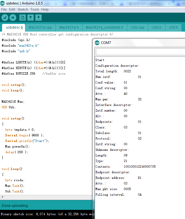
对于USB设备来说,最重要的莫过于描述符。这里介绍如何获得描述符,以及部分描述符的含义。
程序来自http://www.circuitsathome.com/mcu/arduino-usb-host-part-3-descriptors
/* MAX3421E USB Host controller get configuration descriptor */
#include <spi.h>
#include "max3421e.h"
#include "usb.h"

#define LOBYTE(x) ((char*)(&(x)))[0]
#define HIBYTE(x) ((char*)(&(x)))[1]
#define BUFSIZE 256    //buffer size

void setup();
void loop();

MAX3421E Max;
USB Usb;

void setup()
{
  byte tmpdata = 0;
  Serial.begin( 9600 );
  Serial.println("Start");
  Max.powerOn();
  delay( 200 );
}

void loop()
{
  byte rcode;
  Max.Task();
  Usb.Task();
  if( Usb.getUsbTaskState() >= 0x80 ) {  //state configuring or higher
    rcode = getconfdescr( 1, 0 );                 //get configuration descriptor
    if( rcode ) {
      Serial.println( rcode, HEX );
    }
    while( 1 );                          //stop
  }
}

byte getconfdescr( byte addr, byte conf )
{
  char buf[ BUFSIZE ];
  char* buf_ptr = buf;
  byte rcode;
  byte descr_length;
  byte descr_type;
  unsigned int total_length;
  rcode = Usb.getConfDescr( addr, 0, 4, conf, buf );  //get total length
  LOBYTE( total_length ) = buf[ 2 ];
  HIBYTE( total_length ) = buf[ 3 ];
  if( total_length > 256 ) {    //check if total length is larger than buffer
    Serial.println("Total length truncated to 256 bytes");
    total_length = 256;
  }
  rcode = Usb.getConfDescr( addr, 0, total_length, conf, buf ); //get the whole descriptor
  while( buf_ptr < buf + total_length ) {  //parsing descriptors
    descr_length = *( buf_ptr );
    descr_type = *( buf_ptr + 1 );
    switch( descr_type ) {
      case( USB_DESCRIPTOR_CONFIGURATION ):
        printconfdescr( buf_ptr );
        break;
      case( USB_DESCRIPTOR_INTERFACE ):
        printintfdescr( buf_ptr );
        break;
      case( USB_DESCRIPTOR_ENDPOINT ):
        printepdescr( buf_ptr );
        break;
      default:
        printunkdescr( buf_ptr );
        break;
        }//switch( descr_type
    buf_ptr = ( buf_ptr + descr_length );    //advance buffer pointer
  }//while( buf_ptr <=...
  return( 0 );
}
/* prints hex numbers with leading zeroes */
// copyright, Peter H Anderson, Baltimore, MD, Nov, '07
// source: http://www.phanderson.com/arduino/arduino_display.html
void print_hex(int v, int num_places)
{
  int mask=0, n, num_nibbles, digit;

  for (n=1; n<=num_places; n++) {
    mask = (mask << 1) | 0x0001;
  }
  v = v & mask; // truncate v to specified number of places

  num_nibbles = num_places / 4;
  if ((num_places % 4) != 0) {
    ++num_nibbles;
  }
  do {
    digit = ((v >> (num_nibbles-1) * 4)) & 0x0f;
    Serial.print(digit, HEX);
  }
  while(--num_nibbles);
}
/* function to print configuration descriptor */
void printconfdescr( char* descr_ptr )
{
 USB_CONFIGURATION_DESCRIPTOR* conf_ptr = ( USB_CONFIGURATION_DESCRIPTOR* )descr_ptr;
  Serial.println("Configuration descriptor:");
  Serial.print("Total length:\t");
  print_hex( conf_ptr->wTotalLength, 16 );
  Serial.print("\r\nNum.intf:\t\t");
  print_hex( conf_ptr->bNumInterfaces, 8 );
  Serial.print("\r\nConf.value:\t");
  print_hex( conf_ptr->bConfigurationValue, 8 );
  Serial.print("\r\nConf.string:\t");
  print_hex( conf_ptr->iConfiguration, 8 );
  Serial.print("\r\nAttr.:\t\t");
  print_hex( conf_ptr->bmAttributes, 8 );
  Serial.print("\r\nMax.pwr:\t\t");
  print_hex( conf_ptr->bMaxPower, 8 );
  return;
}
/* function to print interface descriptor */
void printintfdescr( char* descr_ptr )
{
 USB_INTERFACE_DESCRIPTOR* intf_ptr = ( USB_INTERFACE_DESCRIPTOR* )descr_ptr;
  Serial.println("\r\nInterface descriptor:");
  Serial.print("Intf.number:\t");
  print_hex( intf_ptr->bInterfaceNumber, 8 );
  Serial.print("\r\nAlt.:\t\t");
  print_hex( intf_ptr->bAlternateSetting, 8 );
  Serial.print("\r\nEndpoints:\t\t");
  print_hex( intf_ptr->bNumEndpoints, 8 );
  Serial.print("\r\nClass:\t\t");
  print_hex( intf_ptr->bInterfaceClass, 8 );
  Serial.print("\r\nSubclass:\t\t");
  print_hex( intf_ptr->bInterfaceSubClass, 8 );
  Serial.print("\r\nProtocol:\t\t");
  print_hex( intf_ptr->bInterfaceProtocol, 8 );
  Serial.print("\r\nIntf.string:\t");
  print_hex( intf_ptr->iInterface, 8 );
  return;
}
/* function to print endpoint descriptor */
void printepdescr( char* descr_ptr )
{
 USB_ENDPOINT_DESCRIPTOR* ep_ptr = ( USB_ENDPOINT_DESCRIPTOR* )descr_ptr;
  Serial.println("\r\nEndpoint descriptor:");
  Serial.print("Endpoint address:\t");
  print_hex( ep_ptr->bEndpointAddress, 8 );
  Serial.print("\r\nAttr.:\t\t");
  print_hex( ep_ptr->bmAttributes, 8 );
  Serial.print("\r\nMax.pkt size:\t");
  print_hex( ep_ptr->wMaxPacketSize, 16 );
  Serial.print("\r\nPolling interval:\t");
  print_hex( ep_ptr->bInterval, 8 );
  return;
}
/*function to print unknown descriptor */
void printunkdescr( char* descr_ptr )
{
  byte length = *descr_ptr;
  byte i;
  Serial.println("\r\nUnknown descriptor:");
  Serial. print("Length:\t\t");
  print_hex( *descr_ptr, 8 );
  Serial.print("\r\nType:\t\t");
  print_hex( *(descr_ptr + 1 ), 8 );
  Serial.print("\r\nContents:\t");
  descr_ptr += 2;
  for( i = 0; i < length; i++ ) {
    print_hex( *descr_ptr, 8 );
    descr_ptr++;
  }
}
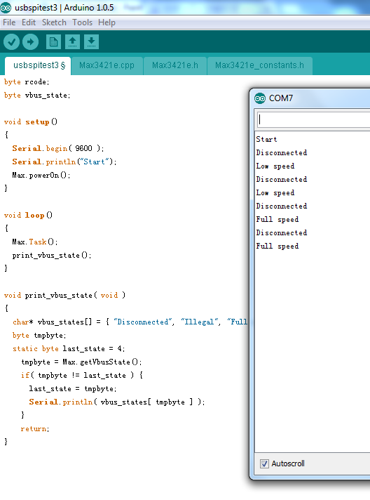
运行结果如下:
手工分析USB的描述符简直就是噩梦…….最好有USB逻辑分析仪【参考1】,抓包解析USB数据非常方便。
多说两句关于【参考1】背后的故事:当年,我在一家国内最大的PC组装企业工作。有一次,加拿大的客户抱怨我们卖出去的机器无法使用他们的一款USB条码枪。我们的机器是 AMD RS780系列的商用机,这个系列的特点是:价格便宜,可以支持很多显示器(如果没有记错的话,用上标准的扩展配件可以同时支持5台显示器的显示,这在当时是很牛x的技术)。只是这个芯片组经常有稀奇古怪的问题,卖出去两三年之后会有客户报告奇怪的问题(销售总是承诺售后保修很长的时间)。比如:台湾邮政的客户惊奇的发现,每天早晨这个机器开机进入桌面之后会出现黑屏闪一次的问题等等。
USB条码枪这个客诉先到前端看了差不多三个月都没有搞定,走流程到全球售后研发这边了。组里正好有一台USB逻辑分析仪,我就拿着实验了一下。最后抓取得结果是这个条码枪和芯片组有兼容性问题,在判断USB设备速度的时候,K J 握手有问题。外国人和中国人在对待问题上差别蛮大,前者通常要求你找到Root Cause,即使时间很长也可以等待,找到之后,如果不是我们的问题,他们也能接受;而后者的要求通常是不管你什么Root Cause, 马上给我个能用的方法就行。他们的逻辑简单得也令人发指,最常见的说法是,我在XXX的机器上看不到现象,那就一定是你们的问题。
只是没想到 Root Cause 找到了,客户也表示接受了,我这边反倒闯了祸。
当时我们刚换了一个Team的主管,BIOS工程师出身,管着下面八九个人。据他所知,在 RS780 芯片组USB配置空间上有个寄存器,可以显示当前某个USB口上是否有USB设备插入。这个寄存器是 RS780芯片组特有的。这个主管坚持非要我去检查这个位是否设置起来。我说,逻辑分析仪结果都抓出来了还看啥啊? 最主要是我太懒了,看问题不一定花时间,但是找机器走流程装系统之类的很麻烦。一番话下去,主管为了不再暴露他对USB的无知,没再说下去,只是脸色变得铁青。从技术的角度来说,我的解释没有办法反驳。好比用示波器看到了波形,知道是硬件问题,Onwer肯定要换成 HW 工程师…….
最后看没看我忘记了,只是后来我在这个主管下面日子不好过了。再后来没办法自己找了个其他部门跑路了,办理转部门的时候这个主管非常“遗憾”的拖了我很久才撒手…….
这个故事告诉我们:
1. AMD 的芯片组不稳定啊!
2. 谦虚谨慎根据情况装孙子很重要,特别是国企类型的企业
3. 懂一半的领导比什么都不懂的更麻烦。
就是这样。
参考:
1.http://www.lab-z.com/wp-content/uploads/2013/02/usbhs.pdf 关于 USB 高速(HighSpeed)和中速(FullSpeed)的区分