之前的文章【参考1】提出了一个问题:为什么在Windows 下SetFirmwareEnvironmentVariable API 只能对有限的几个Variable有用?比如:可以修改“BootOrder”,但是无法修改 “Setup”的值。
文章比较长,大篇幅的罗列代码让文章更像技术手册,没有耐心的朋友可以直接拖动到文章末尾看结论。
我们已经知道 Windows 中的SetFirmwareEnvironmentVariable 函数最终是通过 gRT->SetVariable 调用到 RuntimeServiceSetVariable中的【参考2】 。所以我们可以使用WinDBG追踪代码查看是在哪里返回了错误值。
具体分析:
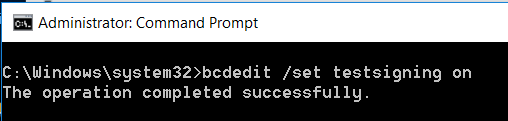
1.下断点
bp hal!HalEfiSetEnvironmentVariable
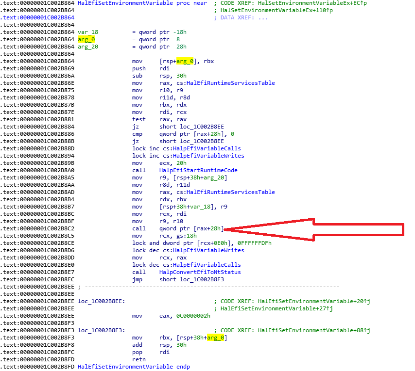
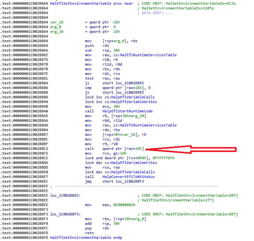
2. HalEfiSetEnvironmentVariable 函数中的call qword ptr [rax+28h] 这个位置就是跳到BIOS 中的SetVariable的入口(再介绍一下 COD文件的生成:
在VariableSmmRuntimeDxe.inf 加入下面的编译指令
[BuildOptions]
  MSFT:*_*_X64_CC_FLAGS = /Oi- /FAcs /Od
在编译过程中即可生成
\Build\KabylakePlatSamplePkg\RELEASE_VS2013x86\X64\MdeModulePkg\Universal\Variable\RuntimeDxe\VariableSmmRuntimeDxe\VariableSmmRuntimeDxe.cod 使用 WinDBG 追踪可以看到执行的代码是 RuntimeServiceSetVariable函数,前面的文章介绍过这样的方法追踪 GetVariable)
3.接下来查看BIOS的代码,因为有 COD文件的存在,我们也能知道每一条函数源代码对应的汇编指令。为了便于实验,在 Variable.c 中的 VariableServiceSetVariable中加入对 80 Port 输出91h的代码,这样可以在 WinDBG 追踪中确定具体“干活”代码的位置。
4.查看 RuntimeServiceSetVariable 函数的返回值部分,可以看到是通过 rax 来返回函数结果的
  001b0	48 8b 54 24 58	 mov	 rdx, QWORD PTR VendorGuid$[rsp]
  001b5	48 8b 4c 24 50	 mov	 rcx, QWORD PTR VariableName$[rsp]
  001ba	e8 00 00 00 00	 call	 SecureBootHook
$LN1@RuntimeSer:
$LN2@RuntimeSer:
; 642  :     }
; 643  :   }
; 644  :   return Status;
  001bf	48 8b 44 24 30	 mov	 rax, QWORD PTR Status$[rsp]
$LN9@RuntimeSer:
; 645  : }
5.编写 Application,调用2次SetFirmwareEnvironmentVariable,第一次是针对BootOrder 变量的,第二次是针对VendorKeys的。
#define VariableGuidStr      "{8BE4DF61-93CA-11D2-AA0D-00E098032B8C}"
#define BootOrderStr         "BootOrder"
	//Get BootOrder
	dwRet = GetFirmwareEnvironmentVariable(
		_T(BootOrderStr),
		_T(VariableGuidStr),
		pBuffer,
		iBufferSize);
	printf("GetFirmwareEnvironmentVariable return value:%x\n", dwRet);
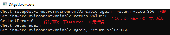
实验结果是前者可以正常设置,但是后者会报错。对于SetFirmwareEnvironmentVariable 函数来说,返回值为0表示出错,不为0是正常【参考3】。
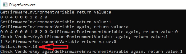
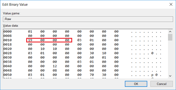
这个错误的含义是【参考4】,同样的这个错误的定义可以在【参考5】看到
ERROR_WRITE_PROTECT
19 (0x13)
The media is write protected.
6.使用 WinDBG 在调用处下断点
kd> u
hal!HalEfiSetEnvironmentVariable+0x41:
fffff800`ce10b8a5 4c8b4c2460      mov     r9,qword ptr [rsp+60h]
fffff800`ce10b8aa 458bc3          mov     r8d,r11d
fffff800`ce10b8ad 488b054c570300  mov     rax,qword ptr [hal!HalEfiRuntimeServicesTable (fffff800`ce141000)]
fffff800`ce10b8b4 488bd3          mov     rdx,rbx
fffff800`ce10b8b7 4c894c2420      mov     qword ptr [rsp+20h],r9
fffff800`ce10b8bc 488bcf          mov     rcx,rdi
fffff800`ce10b8bf 4d8bca          mov     r9,r10
fffff800`ce10b8c2 ff5028          call    qword ptr [rax+28h]
7.不知道什么原因,我在Application 中只调用了2次SetFirmwareEnvironmentVariable,但是 WinDBG 会停下来4次。经过观察前面2次返回值为0x0000000000000000,后面两次返回值0x8000000000000008。
至此,可以确定SetFirmwareEnvironmentVariable 无法修改是因为 UEFI 代码导致的问题,和 Windows 无关。确定这点之后,就可以在 BIOS Source code 中查找是哪里返回了这个错误。最终确定在 \MdeModulePkg\Library\VarCheckLib\VarCheckLib.c 下面的位置返回的 Write Protected
  //
  // Also check the property revision before using the property data.
  // There is no property set to this variable(wildcard name)
  // if the revision is not VAR_CHECK_VARIABLE_PROPERTY_REVISION.
  //
  if ((Property != NULL) && (Property->Revision == VAR_CHECK_VARIABLE_PROPERTY_REVISION)) {
    if ((RequestSource != VarCheckFromTrusted) && ((Property->Property & VAR_CHECK_VARIABLE_PROPERTY_READ_ONLY) != 0)) {
      DEBUG ((EFI_D_INFO, "Variable Check ReadOnly variable fail %r - %g:%s\n", EFI_WRITE_PROTECTED, VendorGuid, VariableName));
     return EFI_WRITE_PROTECTED;
    }
    if (!((((Attributes & EFI_VARIABLE_APPEND_WRITE) == 0) && (DataSize == 0)) || (Attributes == 0))) {
      //
      // Not to delete variable.
      //
      if ((Property->Attributes != 0) && ((Attributes & (~EFI_VARIABLE_APPEND_WRITE)) != Property->Attributes)) {
        DEBUG ((EFI_D_INFO, "Variable Check Attributes(0x%08x to 0x%08x) fail %r - %g:%s\n", Property->Attributes, Attributes, EFI_INVALID_PARAMETER, VendorGuid, VariableName));
        return EFI_INVALID_PARAMETER;
      }
      if (DataSize != 0) {
        if ((DataSize < Property->MinSize) || (DataSize > Property->MaxSize)) {
          DEBUG ((EFI_D_INFO, "Variable Check DataSize fail(0x%x not in 0x%x - 0x%x) %r - %g:%s\n", DataSize, Property->MinSize, Property->MaxSize, EFI_INVALID_PARAMETER, VendorGuid, VariableName));
          return EFI_INVALID_PARAMETER;
        }
      }
    }
  }
从代码中看,这个设定应该是一个安全的 Feature。
总结:BIOS中因为安全设定的缘故阻止了对于一些 Variable 的Write。Windows调用 gRT-> SetVariable 发现返回值是Error,于是 API 也会返回错误值。
参考;
1. http://www.lab-z.com/stu143/ Windows 下BootOrder研究
2. http://www.lab-z.com/haldbg1/ HAL.DLL 中的 HalEfiGetEnvironmentVariable
3. https://msdn.microsoft.com/en-us/library/ms724934(v=vs.85).aspx
4. https://msdn.microsoft.com/en-us/library/ms681382(v=vs.85).aspx
5. 这个错误在 UEFI 中的定义如下
/**
  Produces a RETURN_STATUS code with the highest bit set.

  @param  StatusCode    The status code value to convert into a warning code.
                        StatusCode must be in the range 0x00000000..0x7FFFFFFF.

  @return The value specified by StatusCode with the highest bit set.

**/
#define ENCODE_ERROR(StatusCode)     ((RETURN_STATUS)(MAX_BIT | (StatusCode)))

///
/// The device can not be written to.
///
#define RETURN_WRITE_PROTECTED       ENCODE_ERROR (8)
同样的,编写一个 Shell Application 可以确认就是 Write Protected 错误
Print(L" 0x13=[%r] \n",0x8000000000000008UL);